

can anyone tell me what was operated by the semaphores when they are in the up position??
There are two terminals inside the semaphore - one to power the solenoid and lamp and the other is connected to the solenoid shaft when it comes out
the end of the solenoid coil.
Was there something on the dash to tell you it was "ON"??
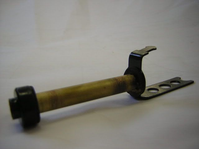
the second terminal is for the blue wire , to the indicator warning light on the speedo (arrow), when the semaphore goes up, a shaft that looks like a huge needle comes down through the solenoid , rubs against a sprung terminal connected to that treminal & completes the circuit
ok thanks... clears that up...
does anyone know how it is internally wired to make that work? where is the needle piece connected into the power circuit?
doesn't that needle piece slide against a brass/copper leaf spring (when the arm extends) to turn on the light in the semaphore?
no... the light is powered from the same connection as the solenoid.
the needle then comes out of the solenoid when it is in the up position to make the connection to the second teminal.
Am just wondering where the connection to the needle is made at the other end?
I think the top end of the needle must be earthed? Isn't the dash warning lamp "hot" (i.e. its at 6V)? This would mean that if the needle is
earthed then current will flow and the lamp will light up.
Use a multimeter to test if the needle is connected to the base plate of the solenoid.
thanks everyone for all your help....
the needle shorts to the frame of the car through the mounting bracket of the semaphore.
have figured out what i need to know to get em working...
thanks.
wanna make mine work after you're finished? :P
hahaha.. sure... what condition are they in??
will let you know after the weekend if what i want to do can be done..
They require some modification and will not look "original" when i finish as i have to completely dismantle them and rebuild them again... and this
requires drilling out the rivets etc...
fingers crossed.
They're in pretty good condition.. everything's there, but there doesn't seem to be enough current to lift up by itself. Are you making a blinking circuit as well?
yes... will all run from 12V in the end and have blinking lights.
you are sooo doing mine...
[ Edited on 19-4-06 by oval TOFU ]
well first step is complete... have them in pieces ready for rebuild.
Do we want photos before i go any further????
happy to post as i go if people are interested.
yes, photos are always good! and use macro mode so it's not blurry!
scuse the ignorance... but what is macro mode and how do i use it?? lol
Yes, post photos! And also do us a wiring diagram of how you make them blink, if you can!!!
| Quote: |
ok... i'll see how these go.
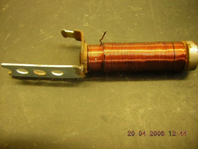
first one is coil removed from semaphore
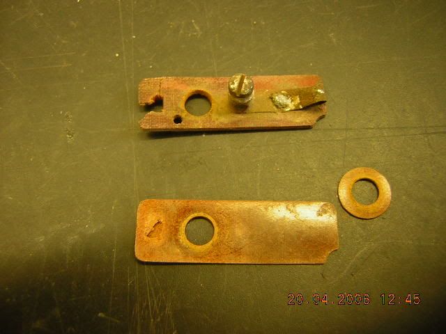
connection segment (with one connector missing)
semaphore without coil attached
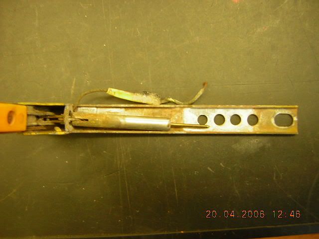
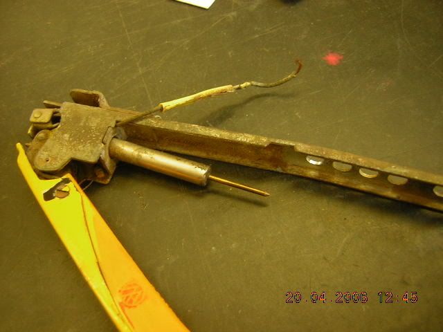
| Quote: |
you silly girl... they will look original on the outside but of course they wont be "original" on the inside coz they need modification....
sheesh... do i have to explain EVERYTHING!!! lol :duh
i'm not touching this with a 10 foot clown pole...:duh
good pics man. more.
[ Edited on 20-4-06 by oval TOFU ]
| Quote: |
| Quote: |
| Quote: |
| Quote: |
maybe you mumble... chicks always complain we mumble...
20ft clown pole...
lol.. went to check out some info today... what i want to do sounds doable but will take me a while to sort out some of the rebuild.
will post more next week when i get back to work.
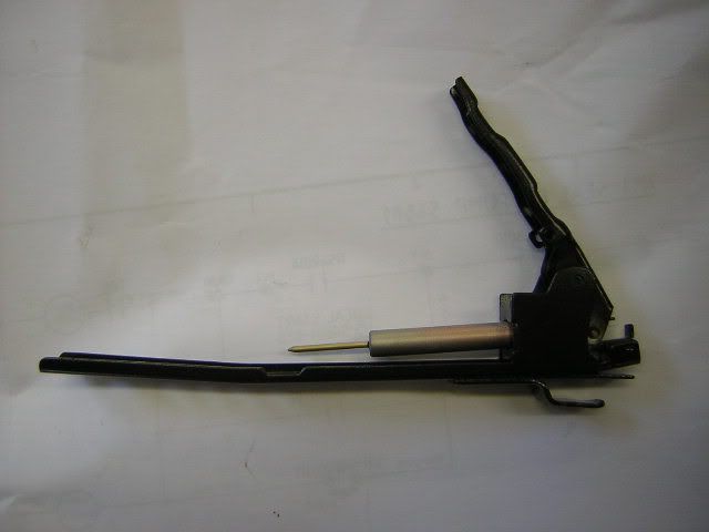
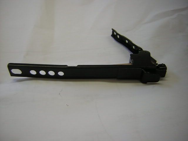
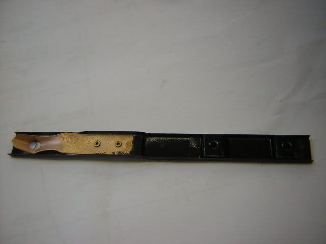
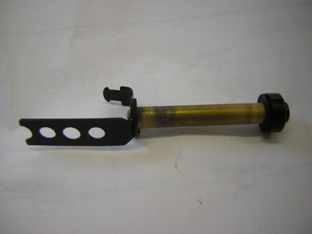
ok.. i have done a test run before i bothered to rebuild the semaphores and pretty them up in case what i wanted to do would not work.
Test was good and shows that it will work how i want them to... so here are some more pics of the work i have done to clean them up... am waiting on
some parts which wont be in till next week so that i can progress them further.
very intersting. I'll be doing mine not far down the track...
Are you rewinding them for 12 V?
| Quote: |