
Second timers guide to beam modification
Dirtbag - October 31st, 2009 at 10:07 AM
Hello again. In the last thread I did called "First timers guide to beam modification" I fitted adjusters and narrowed a ball joint beetle beam.
Well this time I'm going to do the same to a link pin beetle beam.
The beam in this thread belongs to Nickster, so thanks buddy : )
The first thing I did was get out my old jig I made for the ball joint beam and see if it fitted. No it didn't.

I ended up just flipping the jig over and welding new pins onto it to line up with the mounting tabs, and put a bracket on to line the steering damper
mount back up. Now my jig can do both sorts of beams. Yay.

Dirtbag - October 31st, 2009 at 10:14 AM
The idea here is to trim the inside of the shock tower off to allow for more clearance for the bodywork once the beam is narrowed. I'm also going to
slightly lean the towers outwards a little. This beam is getting narrowed 25mm each side.

The first step I took was to mark the trailing arms on one side of the beam, so my stupid brain couldn't get it wrong come re assembly time. I tend
to make things as idiot proof as possible, mainly just for myself : )

The next step is to undo the lock nuts and remove the grub screws from the trailing arms on one side of the beam.

The top trailing arm was hard up against the bump stop, but a nudge with a rubber mallet had the trailing arm off easily enough.

Dirtbag - October 31st, 2009 at 10:20 AM
Next, undo the lock nuts and remove the grub screws from the centre of the beam. These hold the torsion leaves in place.

When you slide the trailing arms out, be sure to remove the seals so they don't end up on the ground or lost.

I kept the trailing arms on one side to make removing the torsion leaves easier. I also marked each torsion leaf pack so I'd know how to re assemble
them again.

Once the beam is stripped down, I cut the beam mounting tabs off and cleaned up the beam tubes.

Dirtbag - October 31st, 2009 at 10:27 AM
The adjusters I used are Empi sway a way type ones. Nice and easy to use.

I swear by using damp course strips for marking tubes. If all the overlaps are on top of each other, then it will be a perfectly straight line to mark
with a texta.

I also marked a line along the tubes in line with where the original torsion leaf locating grub screw was, so I can align the adjusters later.

All the marking out is now done. Because I'm narrowing the beam from the centre, I allowed for 50mm for the adjusters, and then 25mm a side for the
narrowing, so there is 100mm marked in the centre of each tube.

Dirtbag - October 31st, 2009 at 10:36 AM
Once I'd breathed in and chopped the nice shiny beam into pieces, I clamped it onto some angle iron to keep everything straight and sat the adjusters
into place.

I made sure there was a sufficient gap in between the adjuster and the beam tubes to allow for good welding penetration. Leaving a gap means you
don't have to bevel the edges, so I leave a gap as I am lazy : )

Once everything was lined up and ready to be tacked in, I rotated the block inside the adjusters around so the threaded hole wasn't visible and also
places an old bolt through the hole in the adjuster bracket to keep any unwanted welding spatter out of the threads.

If you're having a go at this yourself, just make sure there's more weld below the surface than on top of it.

I gave this beam a bit of a sand up after welding the adjusters in, but it's really a pointless exercise. It just comes down to personal choice. On
my volksrod, the welds are left unground.

Dirtbag - October 31st, 2009 at 10:46 AM
Once all that was done it was time to re fit the beam mounting tabs. This is where making a jig makes the job a lot easier.

The link pin beam mounting tabs aren't welded all the way around like a ball joint beam is. To keep it looking sort of standard, I welded the tabs on
the same way as original.

So after that I had it looking like this.

This beam had the top shock mounts drilled out, and the holes were pretty flogged out, so I decided to just machine up new bosses to replace the top
mounts when I trim the shock towers down.

I cut the inner side of the shock tower off, which includes a heap of rotten spot welds. I also cut the top shock mount out.
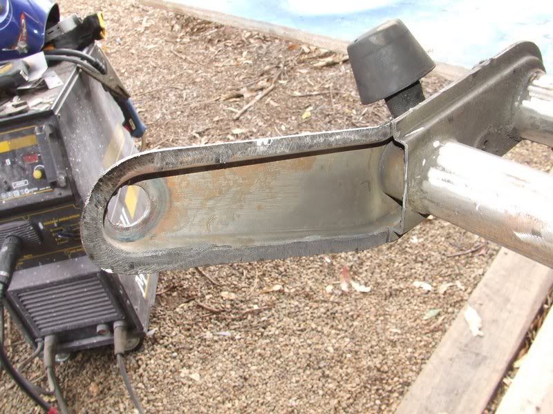
Dirtbag - October 31st, 2009 at 10:54 AM
I also notched the shock tower and cranked it outwards a little to give more body clearance.
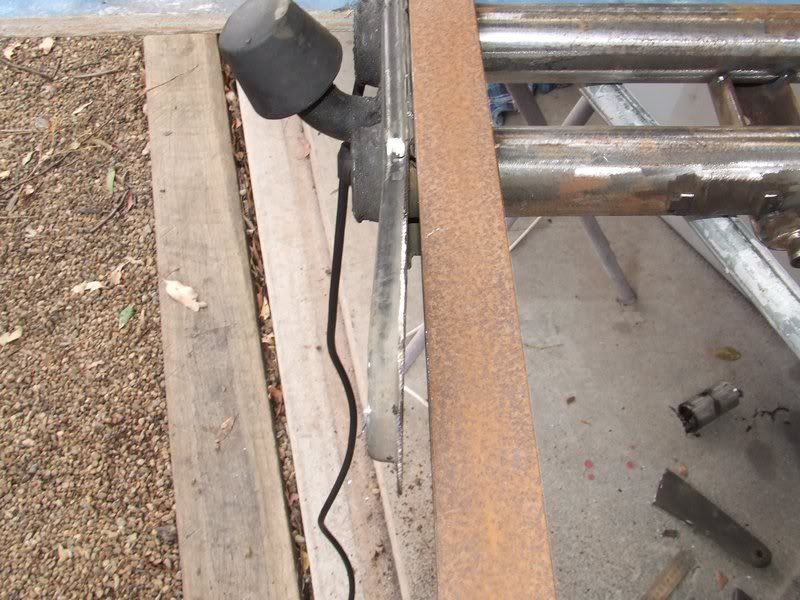
You can see here how hammered the old shock mounts were.
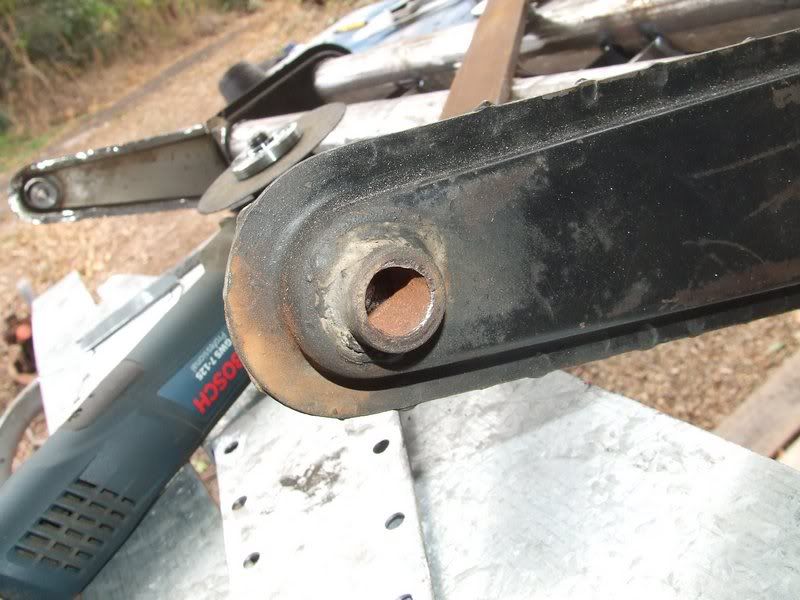
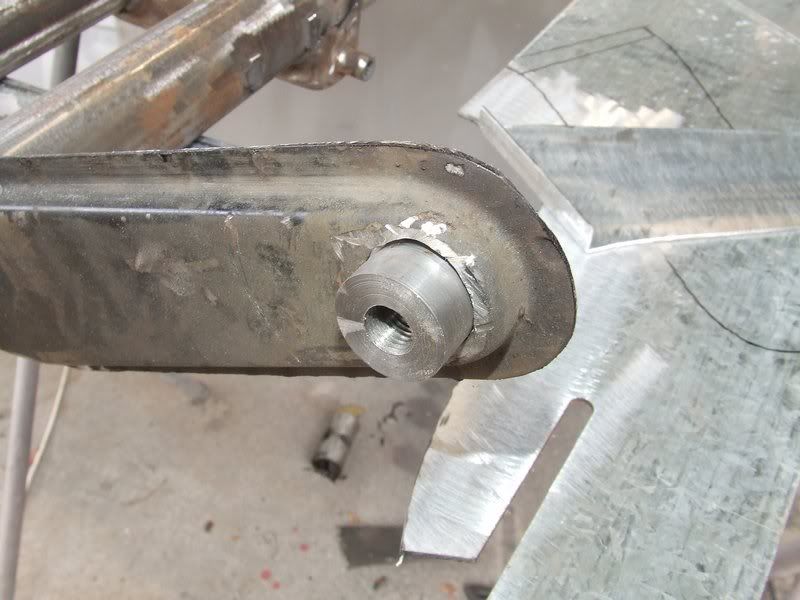
I also decided I was going to make the new top shock mount a bit bigger, so I used the die grinder to make the hole in the tower bigger.
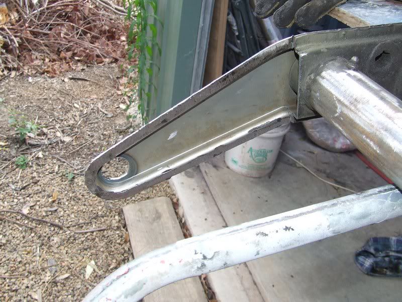
Dirtbag - October 31st, 2009 at 10:59 AM
I found a piece of scrap rod to machine down for the top shock mounts.
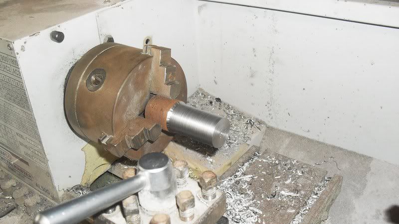
I'm going to put a 12x1.5mm thread in these mounts so I bored a 10.5mm hole so I could run the tap through.
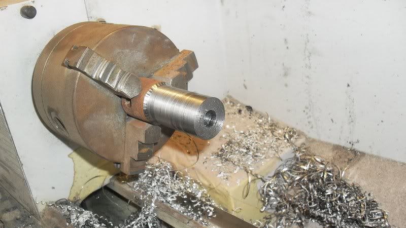
Here's the finished product. Simple, but all these little things add to the time it takes. Lucky I like this stuff then hey?
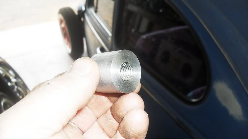
Then I just had to make sure the new mount fitted in the hole in the tower.
Dirtbag - October 31st, 2009 at 11:07 AM
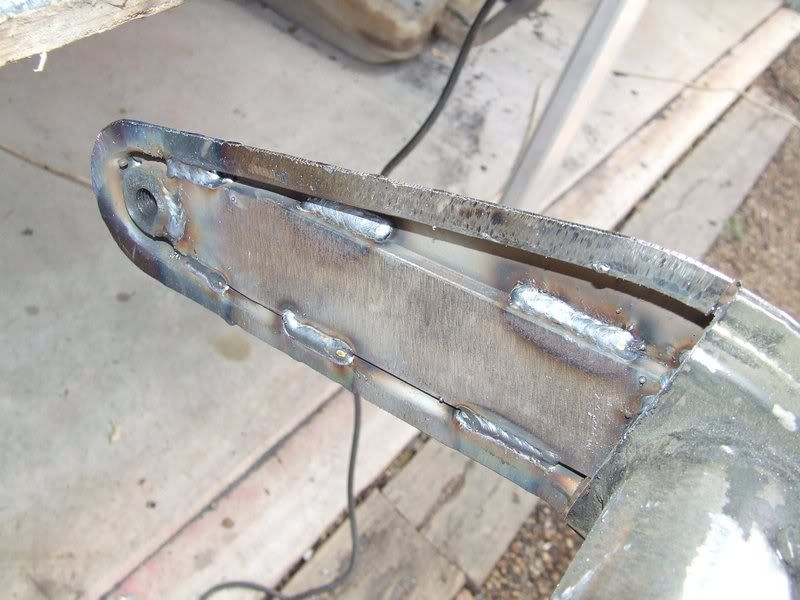
I then made up a new inner shock tower to put a bit of strength back into the tower. You can see how much clearance has been gained by trimming the
tower down.
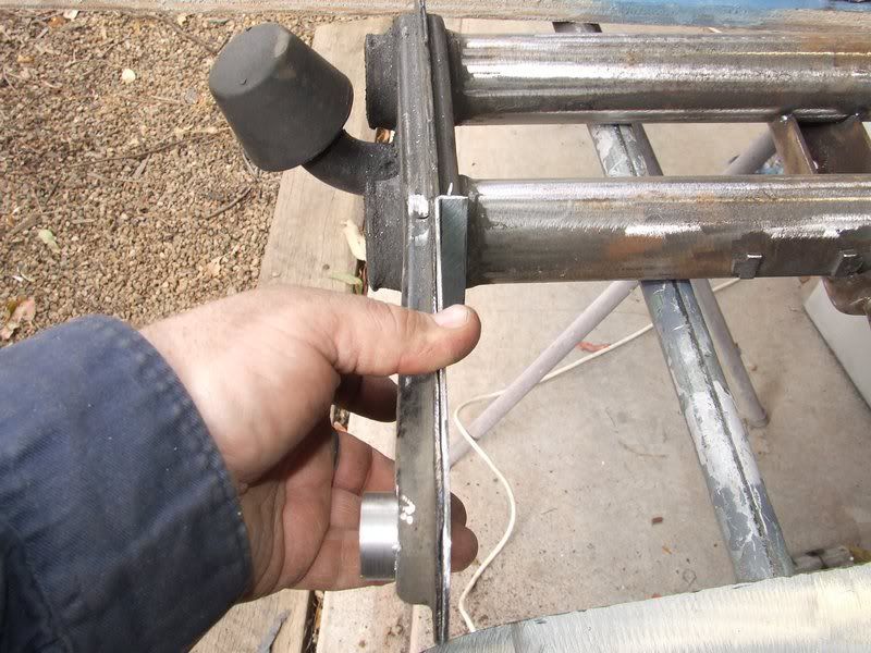
Before I seal the tower back up, I welded a piece of 40x10mm plate into the tower, joining the top shock mount to the top tube of the beam. Can't
hurt.
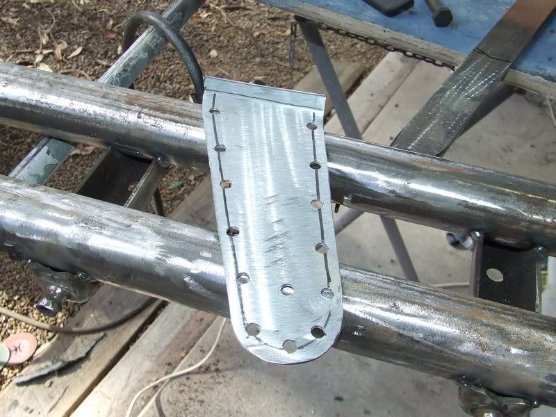
Before I weld the new tower skin back on I drilled a row of holes around the outside so I can plug weld it back into place. I also drilled a hole at
the top so I can weld it onto the back of the new top shock mount.
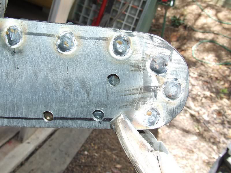
You can see here as I've started the plug welding, the hole in the middle of the plate. Through that hole you can see the back of the top shock
mount.
Dirtbag - October 31st, 2009 at 11:32 AM
With all the welding done and sanded down, it looked like this.
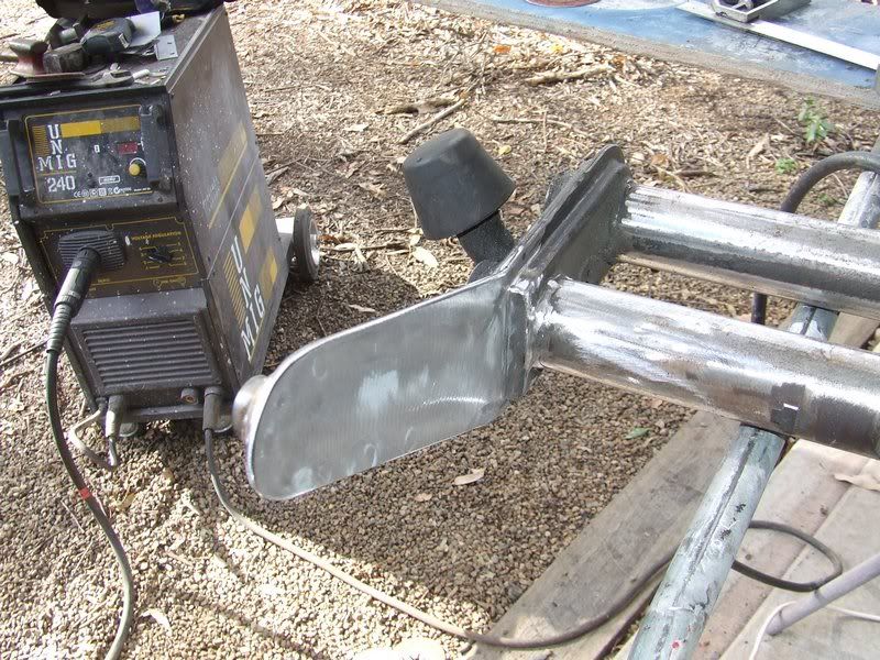
I also ran a full weld around the outside of the new top shock mount.
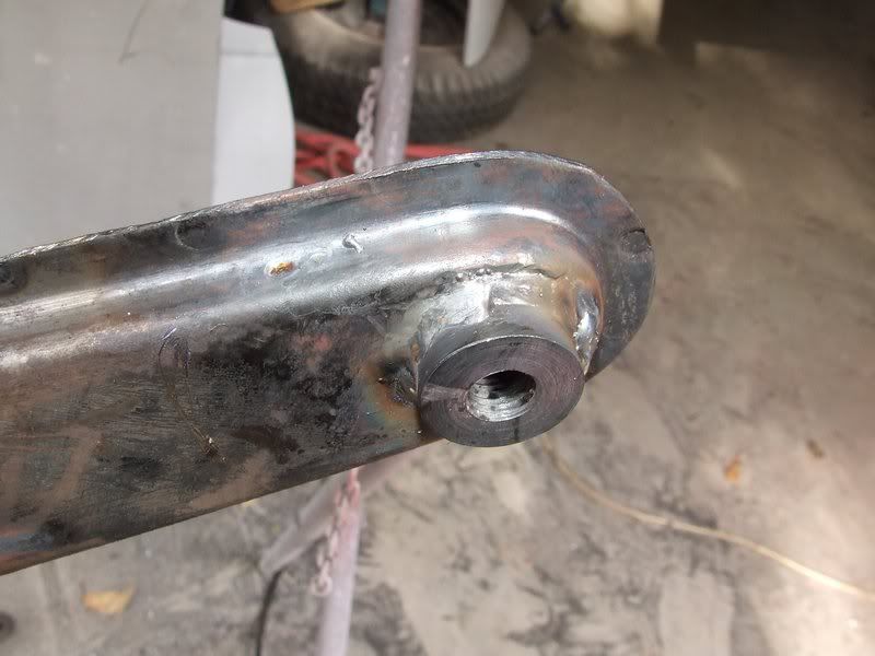
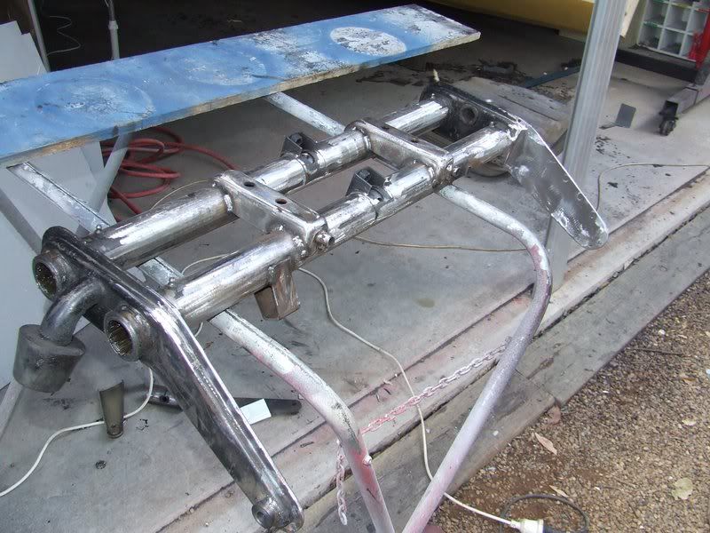
So after I did the other side and re fitted the steering damper mount the beam housing was finished. Oh, I also ground the right hand steering box tab
off, so the steering box can go over the top of where it was. Make sense?
Dirtbag - October 31st, 2009 at 11:41 AM
Next job is to cut the torsion leaves down. I like to tape the ends up with 50mm masking tape, as it's easier to mark than greasy leaves. I marked
the 25mm each side, and also measured the mark for the new grub screw dimple, which was 10mm from the centre of the dimple to the end of the
leaves.
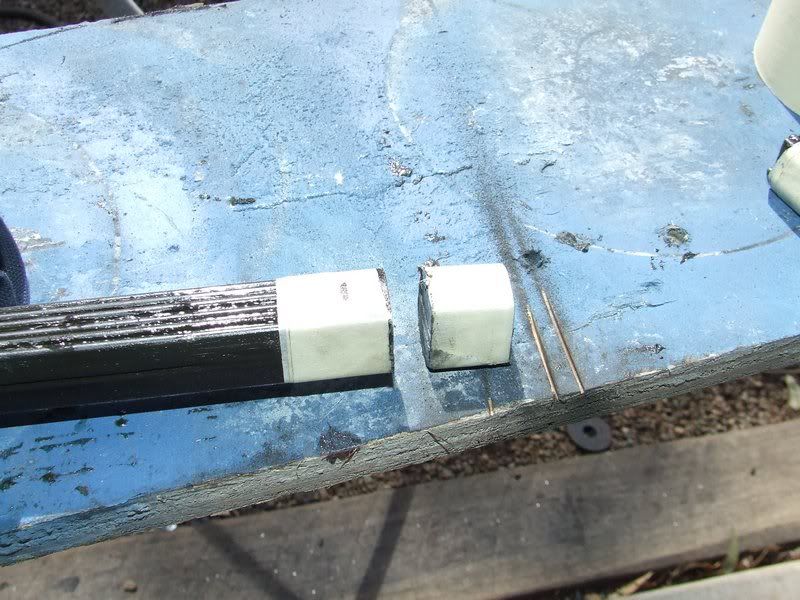
I used a 6mm drill bit to get the depth I wanted for the new dimple, and then ran a 13mm drill to open the dimple up. Someone said somewhere to use a
14mm bit, but my 13mm bit fitted the original dimple perfectly, so I used that.
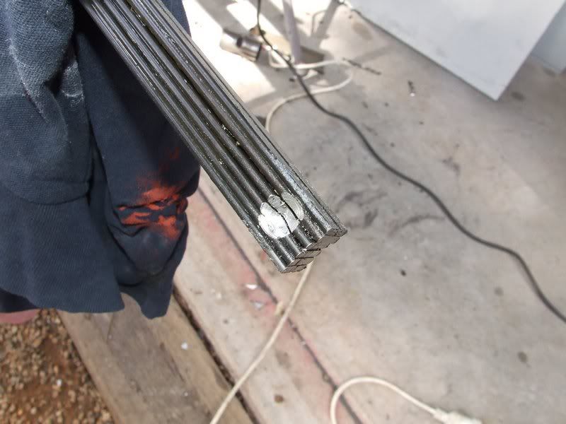
Once all 4 dimples are drilled out, I reassembled the beam, which I'd given a quick coat of matt black. Because I'd labelled everything during
removal, my pea brain didn't have to try and remember anything : )
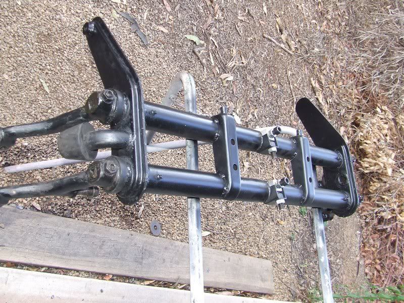
Apart from the adjusters, I don't think this modification is too obvious, which is good. Once it's fitted, the shock tower mods shouldn't really be
seen. We'll find out when Nick fits the beam to his car.
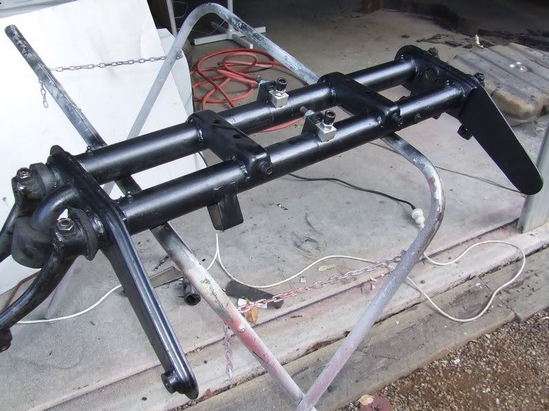
Dirtbag - October 31st, 2009 at 11:50 AM
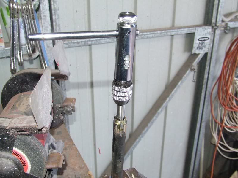
All that's left now is the steering arms. I only have right handed thread taps, so had to make sure I didn't cut off the end with the left handed
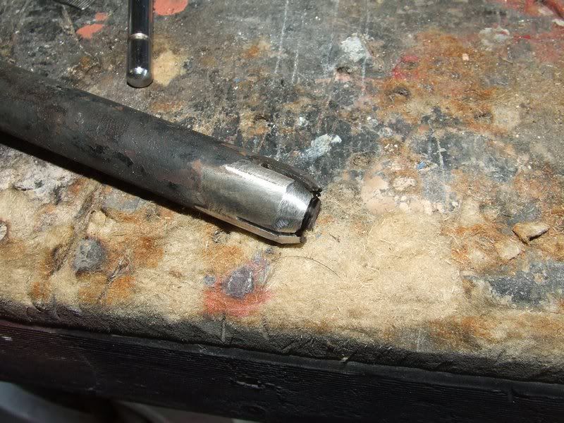
thread. The locking system on the link pin beams requires the end of the steering arm to have these 4 slits cut into it and a tapered end.
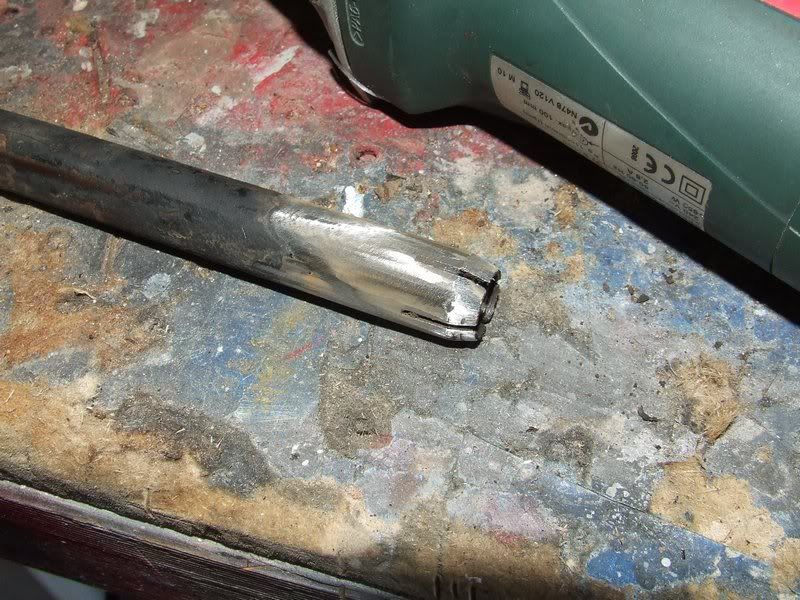
Once I'd cut the 25mm off each steering arm, I ran the tap through so there was more thread inside for wheel alignment adjustment. The tap is
14x1.5mm.
I then re cut the slits and ground the taper into the end of the steering arm.
Dirtbag - October 31st, 2009 at 11:57 AM
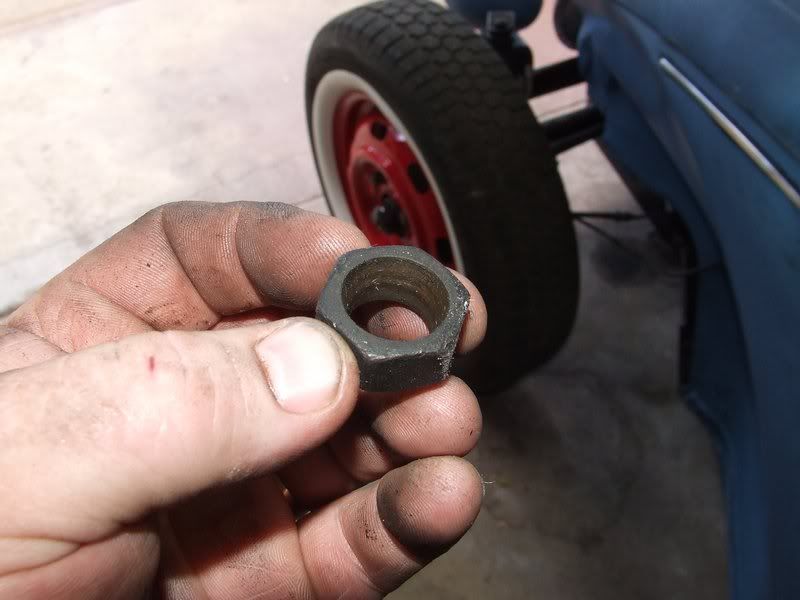
This is the locking nut. It has a tapered hole so as it gets tightened against, the taper forces the 4 sections of the steering arm where the slits
are to push into the thread on the tie rod end, making it very hard for it to undo. It's a pretty good system really. Easy to copy too which is
nice.
This is what it should look like when it's reassembled.
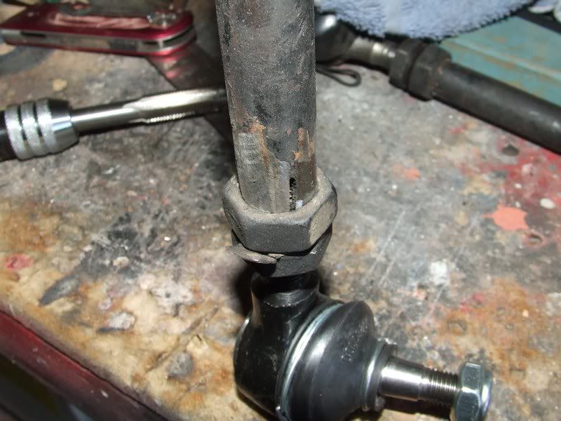
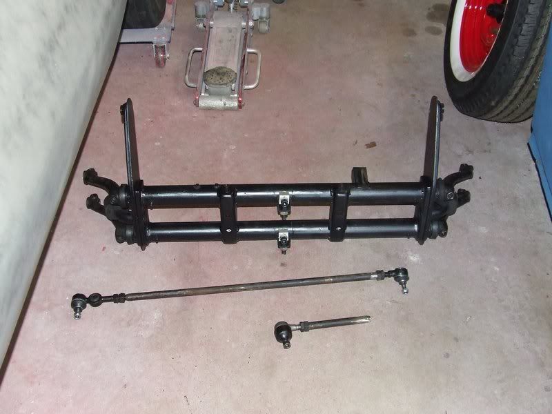
And here's the finished product. Nick said he'd send some pics of it fitted and hopefully let me know if there were and dramas fitting the beam.
I'll post them up here anyway to help the thread.
OK, well that's it for now, so tata. : )
Dirtbag.
aka Tim Johnston.
Dirtbag - October 31st, 2009 at 12:10 PM
I hope these threads are of some help to someone. I'm certainly no expert, but I'm happy to share what I do know.
psimitar - November 1st, 2009 at 11:23 AM
Excellent job there dude 
Looking forward to getting mine back 
loved the volksrod too 
trickysimon - November 1st, 2009 at 11:46 AM
Great work there 
Always love these sort of threads..
Nickster - November 1st, 2009 at 05:53 PM
Tim, nice work mate, I fitted the modified beam back in the car today and she fits perfectly, no dramas at all.
I still have to get the right length bolt for the top of the shocks.. and I will source a proper sway bar for a narrowed beam too.
I took a few pics as promised. This won't be the final ride height, it will probably sit a little higher than this, I got impatient and wanted to
take her out for a spin! The tyres do rub at this height when turning so it has to come up a bit anyway. Plus it sitting on the bump rubbers, which
can't be good.
The thread looks great and I can see how much work you did on those towers, so thanks again!
Catch you soon.
Nick
Nickster - November 1st, 2009 at 05:55 PM
..
Nickster - November 1st, 2009 at 05:56 PM
a perfect fit!
Nickster - November 1st, 2009 at 06:01 PM
even though it's had 2" removed from the width I don't think it's that obvious, possibly because I'm running a disc brake conversion so I have 4
lug to 5 lug converter plate in place which steps it out a bit.
Camo - November 1st, 2009 at 06:18 PM
Tim,
Great job and a great writeup. You make this modification look easy (I'm sure its a little harder) and I'm sure it will encourage others to have a
go in the future. I have a spare beam here that I can practice when time permits.
Well done champion.
Kev
P.S. I think this should be a sticky !! 
Dirtbag - November 1st, 2009 at 06:27 PM
Thanks for the kind words guys, and Nick, what a relief it fits hey : ) Your tyres look fairly bulgy on those rims so you could also go to a smaller
tyre if you needed some more clearance. Thanks for posting some pics of it fitted. Your car looks awesome. I love it.
psimitar - November 2nd, 2009 at 06:25 PM
Nick, what size tyres you got fitted? 165 is the biggest you should pop on a 4J rim. and those look like an 80 profile so maybe some 165/65's will
work.
You hit nail on head tho and it's those 4 to 5 lug adapters that are doing it. What disc kit did you use? Volksconversion, Airkewld, CSP all do wide
5 kits that do increase the track a little on some but not as much as the adapters cos the wide 5 is part of the hub  Of course, this would be an expensive fix
Nickster - November 2nd, 2009 at 07:09 PM
they're 165 R15 87S - New tyres are on my list as these look just a big too big. Do you know what the alternative to a white wall insert is - I've
seen tyres with a white, and some with a red, strip that appears to be moulded into the sidewall.. bet they are $$! Either way something with a lower
profile is the go I think...
Cheers for the advise about the disc kits. I bought the car with the kit in place so I couldn't tell you what kit it is! ALl I know is it works well

psimitar - November 3rd, 2009 at 06:38 PM
yea those tyres sound like 80 profiles. 165/65's should stop your rubbing and still look good 
As for sidewall stripping you used to be able to get kits in the UK but they didn't last long before they peeled or cracked. proper ones will be
$$$$$.
Glad the kit works well just a shame it increased the track width. Still with the tyres done you should be laughing
hellbugged - November 3rd, 2009 at 08:40 PM
good stuff and nice work!
might be an idea to cut the bump stops and rotate them as well next time.......
from memory, the positioning of the adjusters in this example will provide Low, LOW and LOWER ride heights..........tends to be nice to be able to get
it up near stock height on the highest settings.....just a thought, will be interesting to see once Nickster gets the time to have a play
Dirtbag - November 3rd, 2009 at 09:13 PM
Thanks for the advice hellbugged, I'm happy for any extra info. As for the adjusters, I must admit I'm a bit of a low freak : )


 Of course, this would be an expensive fix