
What has Dave Been Up To? 29th AUG 2015: 10.66@126.09mph!!
dangerous - October 31st, 2006 at 01:22 PM
Well, after the Warwick '06 meet, I decided to make some changes to the car.
These include :
Purchase some quality nozzles for the fuel system and get it re-flowed,
Adding an MSD 6AL,
Putting stock width guards on the car,
And, upgrading the CV joints.
The CVs and flanges were robbed off my crashed Chassis car, and are Commadore items.
The drive flanges and stubs have had locating rings welded to the standard items.
Some clearancing of the bump stop bracket was needed.
These CVs use a 28 spline axle the same as a 930 CV joint.
My axles are made by Romac here in Brisbane, and are 400mm long.
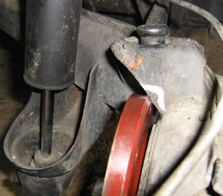
You can see how I cut a groove in the outer, to reduce some of the added weight.
This is pretty conservative, because I dont want a failure.
Perhaps I will remove a little more weight later.
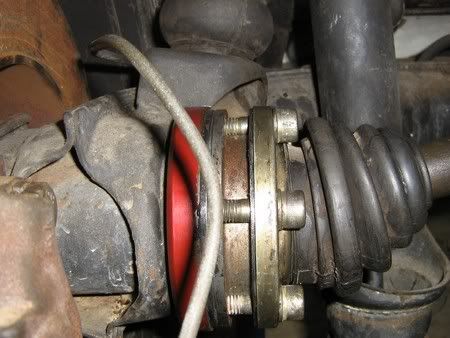
[ Edited on 31-10-2006 by dangerous ]
[ Edited on 2-11-2006 by dangerous ]
[ Edited on 14-3-2007 by dangerous ]
dangerous - October 31st, 2006 at 01:33 PM
I got this old MSD from a speedway guy that sold me a whole heap of his old VW stuff.
It was tested OK, but it would not work on the dyno.
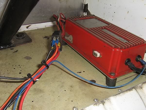
I chose to use my Vanagon Wasser Boxer Dizzy,
so that if I have a problem with the MSD, I can bypass it and use the original system.
This is why the wiring is a mess, at the moment.
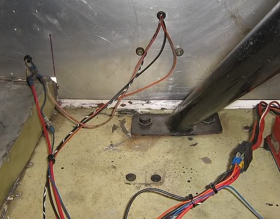
The MSD unit has to be supplied with a 12 volt direct supply,
and then there is a black, and an Orange wire that go to the coil.
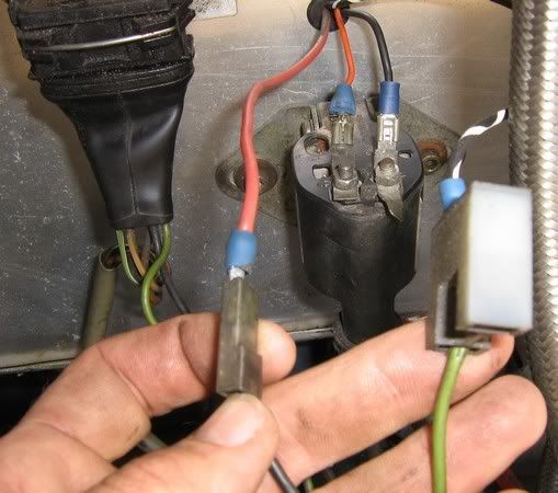
The original VW wires (black for +ve, and green for -ve), are disconnected and one still gets 12 volts, whilst the green one now triggers the MSD
white wire.
dangerous - October 31st, 2006 at 01:47 PM
All my connections have been soldered as well as crimped.
It looks likely that the former owner had a bad connection where the MSD dizzy wires,
connect to the purple and green wires on the 6AL.
I have chosen to use the white trigger wire instead.
The other wires will be left un-used.
Here is where the fat power wire is connected to 12 volts, and also the earth wire.
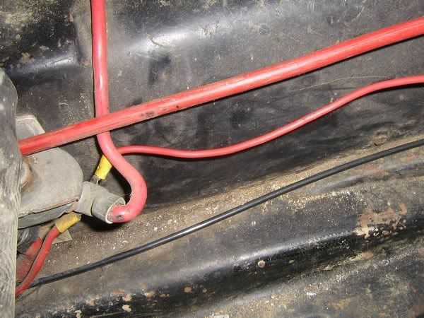

All the VW wiring is still in place, in case of a problem.
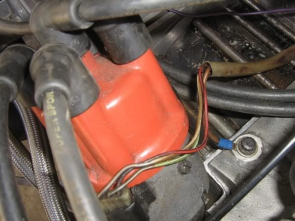
The car started up fine and it is now even more responsive than before.
The muliple sparks at cranking speed are impressive!
The spark actually makes a screech sound when it fires!
I put it on the 6000 limitter to make sure it works...man what a sound!!
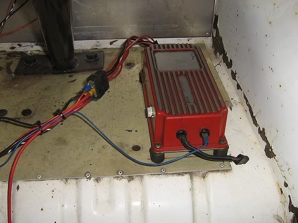
I mounted the unit on rubber spacers to stop vibration damage.
It is on the package tray at the back of the car.
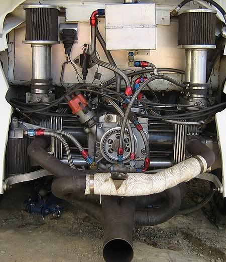
This is a photo of the engine with the coil and factory module mounted on the 1.5mm aluminium firewall.
dangerous - October 31st, 2006 at 01:57 PM
The fuel system is my constant tinkering project.
Yes, EFI is better, but on alcohol(methanol) I believe I can make this sytem run 99% as good as EFI.
I love to tinker and make things better, so I purchased some Kinsler Nozzles,
that are flow tested to be within 1% of each other in their pounds-per-hour rate.
This test is done at three different pressures.
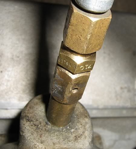
The system has been re-flowed by Farrer Fuel Injection, and the hi-speed lean-out is now opening at the power peak of 7000 rpm.
At warwick it was opening at 7600, and this was only just before my 7800 shift.
dangerous - October 31st, 2006 at 02:05 PM
The narrower guards at the rear is more of a project than you would think.
Being that this car is IRS, and has disc brakes, and 8.5 inch slicks,
a stock width guard is a tight squeeze.
Again, with parts robbed from the chassis car,
I have brought the hubs in about 20mm from their original position.
I used a VW front rotor, and type three hubs to mount the wheel,
and a bracket for 914 calipers.
This required the back of the hubs to be machined off to get the caliper central with the rotor.
I also then needed a spacer for the axle nut.
All this work has allowed stock guards to fit, and all for Vanity.
I want the car to look a little bit more like it should.
More photos soon....
Dasdubber - October 31st, 2006 at 06:12 PM
You have been a busy boy Dave!
dangerous - October 31st, 2006 at 07:34 PM
The calipers that I am using are the late model type 3.
These have the same bolt spacing as my old 914 calipers, but use larger pistons.
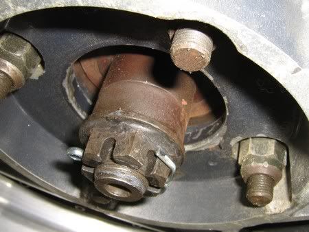
Here is a shot of the spacer that takes upn the difference if what I took off the back of the hub.
It is made from the snout of an old drum, and is about 20mm(can't remember exactly)
This is a couple of views of the caliper brackets. They are fabricated from steel.
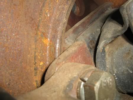

Being that they are fabricated, they would never pass a RTA inspection,
but I welded them correctly, and they are regularly crack tested.
These have served me well for over 14 years.
Perhaps I will make some from aluminium to save weight...or perhaps I will just leave them as is.
Stanley - October 31st, 2006 at 07:53 PM
Nice work Dave.
It's lucky you've got some work to do on the car....don't want those hands going soft...I almost thouight that was a hand models hand in one of the
earlier picks....
pete wood - October 31st, 2006 at 08:44 PM
love it dave, you are a craftsman. 
btw, just looking at your throttle bodies. are they are custom job or are they off a particular model of something ot other?
dangerous - October 31st, 2006 at 09:27 PM
The throttle bodies are old ARPM/Bugpack IDA pattern throttle bodies,
opened up to 56mm.
Those callouses on my hands were not from work...but yeah, they do look like model hands.
I will stop right there with the jokes about the moisturiser!!
Boostn - October 31st, 2006 at 09:48 PM
The guards are coming Dave,
one down and half way through the second one, got to love Sundays.
dangerous - November 1st, 2006 at 06:39 AM
Thanks Nick. You are a champ.
I really appreciate this.
Stanley - November 1st, 2006 at 08:16 PM
Hey Dave, what are those coils like? I was looking at one at the local go fast shop. Are they any better than a standard GT40 etc?
dangerous - November 1st, 2006 at 08:26 PM
| Quote: |
Originally
posted by Stanley
Hey Dave, what are those coils like? I was looking at one at the local go fast shop. Are they any better than a standard GT40 etc?
|
I am not sure about why they are the go Andrew.
This is just an off the shelf electronic coil.
In theory, the GT 40 would work with the stock electronic system as well,
but perhaps someone who knows more will chime in.
This one has served me well for many years.
dangerous - November 2nd, 2006 at 11:53 AM
Try this link :
http://www.sportcompact.net.au/Dave_Butler.php
dangerous - November 2nd, 2006 at 02:35 PM
Yesterday I picked up a two step module selector to borrow,
from Craig at Crankshaft Engineering.
It has two different rev limiting "chips".
The lower RPM one is for the start, and the higher one is for the over-rev protection.
I am planning to leave the start at 5000, and shift at 7800 with an 8000 chip for safety.
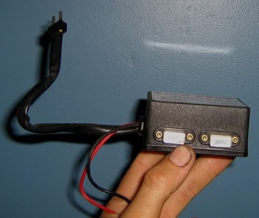
The lower limit applies when 12 volts is switched to the box.
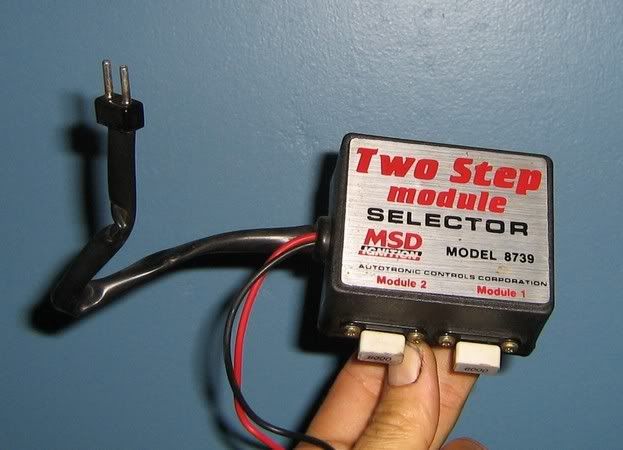
I plan to trigger this 12 volts with a micro switch on the clutch pedal.
This way, when I leave the start, my accellerator will be flat to the boards,
and the engine will not see any more that 5000 rpm.
dangerous - November 2nd, 2006 at 02:41 PM
Switch goes up...
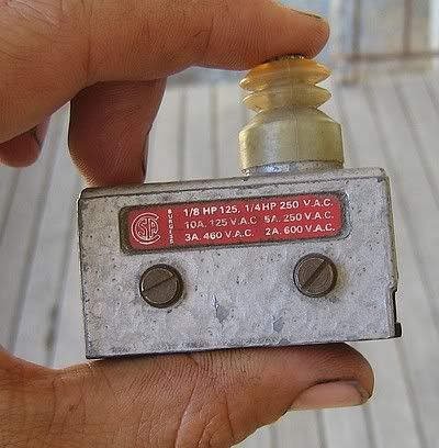
Switch goes down...
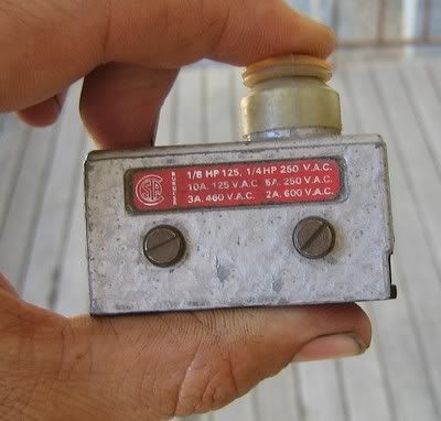
Stanley - November 2nd, 2006 at 05:23 PM
must be a test and tune coming up
and can I also add....nice suit.
Does that make your crew the "john butler trio" sorry.....:o
[ Edited on 2-11-2006 by Stanley ]
Adolph - November 3rd, 2006 at 09:33 AM
Hi Dave
How much did they charge for the custom axles.
I need to have some made for my auto box, also have holden CVs.
Thanx and great job
Hermann
dangerous - November 3rd, 2006 at 01:20 PM
Hi Hermann,
I bought them some years ago and they were under $400 for the pair.
Have all you dimentions ready, including the circlip groove size and location you want,
when you ring.
They are classed as a fully floating 28 spline axle(90 degree spline).
You may have to go through a romac dealer, in which case they will tack on their profit margin.
Try direct first, once you have a sketch of what you want.
DB
Boostn - November 4th, 2006 at 12:05 AM
Hey Davo,
you need to u2u me a postal address as I plan on doing some OT these few days off.
dangerous - November 10th, 2006 at 06:28 PM
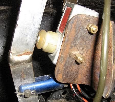
Here is where I mounted the 2-step unit.
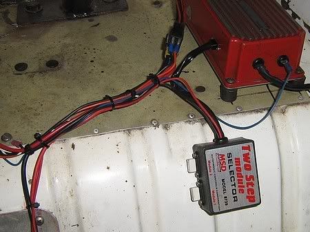
I decided to mount the 2-step switch on the staging brake,
because there was no room near the clutch pedal.

When the staging brake is applied,
there will be 12 volts sent to the 2-step box.
To prevent the lower rev limit operating in the burnout box,
I installed this switch.
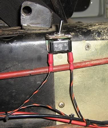
It is turned ON when the burnout is completed.
If the engine hits the limiter in the burnout, the car stops producing HP, and the burnout will be crap.
So I try to control the throttle to maintain the RPM at about 7000 to 7500.
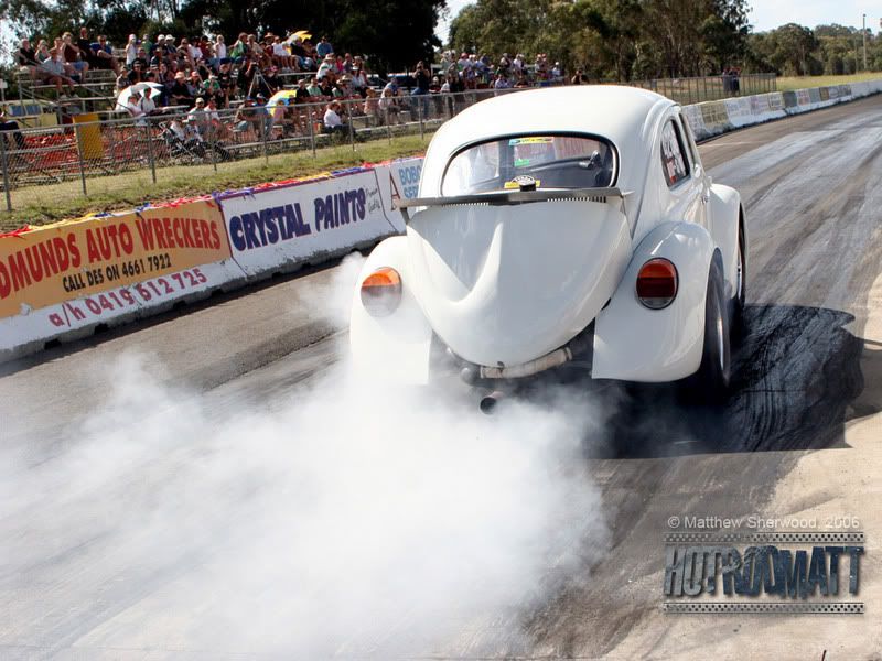
Thanks HotRod Matt!
[ Edited on 10-11-2006 by dangerous ]
dangerous - November 15th, 2006 at 10:55 AM
Yesterday I made up some rev limit chips from some resistors, and some MSD chips that I had that were out of my range.
This photo shows the multi meter and the chips that I have to set the rev limiter.
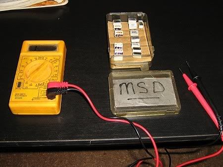
Each chip has a set resistance inside, so I need to set the multimeter to the 20K Ohm scale to see how they compare.

Here I am testing one that I made.
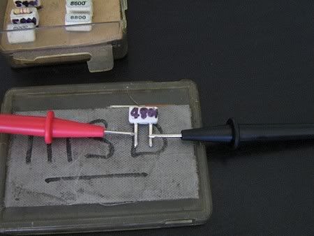
I measured all the ones that I had and determined that I needed some resistors between 3 and 4 K Ohms for my start line RPM of around 5000 revs.
[ Edited on 15-11-2006 by dangerous ]
dangerous - November 15th, 2006 at 11:11 AM
The next step was to find some doner chips to sacrifice.
These ones on the 9000 rpm scale will do fine.
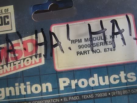
I peel off the sticker, and inside is a precision resistor that I picked out, so that I can put in the replacement.
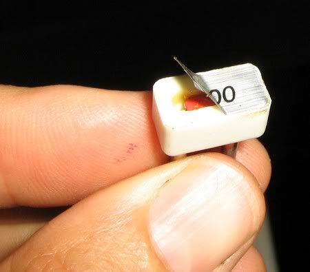
Based on my measurements with the multi meter, I got some resistors that were within my range,
and soldered them into the MSD carcass.
You can get these from Dick Smith or Tandy.
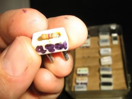
The legs are hollow, so I unsoldered the old, and installed the new.
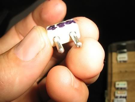
Now all that was left was to try them in the car and test the limiter using the tach.
3.29 K Ohms was 4800 rpm.
3.58 K Ohms was 5100 rpm.
3.87 K Ohms was 5400 rpm.
and 4.22 K Ohms was 5800 rpm.
From the MSD chips that I had , 3000 chip measured 1.9 K Ohms and the 6000 chip measured 4.57 K Ohms.
It would have been quicker to just buy the correct chips from MSD, but I want to try a few different launch RPMs before I buy, plus I like to tinker
too.
Boostn - November 15th, 2006 at 11:52 PM
| Quote: |
plus I like to
tinker too.
|
HA HA !!!!!!!!
dangerous - December 13th, 2006 at 11:17 AM
Latest update is that I have fitted my new, stock-width, guards at the rear.
Before:
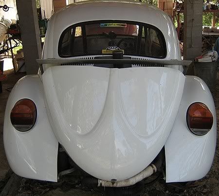
After :
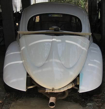
One point during the change over was that I used a tungsten burr to make the holes,
rather than using a drill that will grab the fibers and tear the hole much bigger.
Thanks to Nick for this advice.
Nick from Vollkommen Art supplied the mudguards and the quality and fit was the best I have seen.
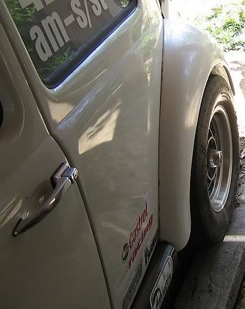
As it was before:
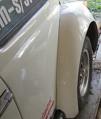
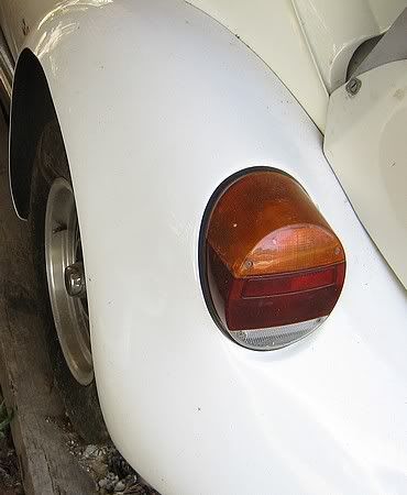
Another point was that I did each hole one at a time,
by marking out each one with the hole in the body.
I started from one end of the mudguard, that is most important to appear
correct alignment with the other body parts.
For most this will be correct alignment with the rear apron.
dangerous - December 20th, 2006 at 02:45 PM
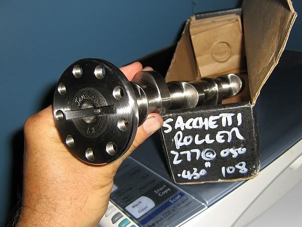
New cam from other post:
Boostn - December 28th, 2006 at 12:07 AM
Dave,
just because it's Christmas, it does not mean you can get slack with updating your post!
what's the latest? guards on yet?
post a pick up.
humpty - December 29th, 2006 at 12:13 AM
Yeah... Come on Davo!!!
lunar_c - January 5th, 2007 at 02:37 AM
You are .. hardcore.
I am a competent mechanic myself and I love to tinker.. but you're obsessed!
It's a pleasure to watch. Your car is amazing!
Regards,
Ben


