| [ Total Views: 222524 | Total Replies: 708 | Thread Id: 38560 ] |
| Pages: 1 .. 3 4 5 6 7 .. 24 |
|
|
 56astro 56astro
Custom Title Time!
    
Posts: 1772
Threads: 74
Registered: August 25th, 2002
Member Is Offline
Location: The Nambucca
Theme: UltimaBB Pro Blue ( Default )
Mood: Pobjoy Powered with twin ignition & soon to be EFI'd
|
| posted on December 13th, 2006 at 07:44 AM |
|
|
OK Daimo, Monday and Tuesday (your work-on-engine days) have just passed. Where's the update and pics - you know we all love pics.


VW car, VW engine ...... keepin it "real"
35MPG on 101.3kPa |
|
|
 hellbugged hellbugged
A.k.a.: Daimo Pell
23 Windows of Awesome
48's and straight cuts
       
Posts: 5080
Threads: 116
Registered: April 17th, 2003
Member Is Offline
Location: Nambucca Valley NSW
Theme: UltimaBB Psyche Blue
Mood: Couldn't care less
|
| posted on December 13th, 2006 at 09:02 PM |
|
|
ooorkay, a few updates lost in the crash astro, it's coming along.......
washed up the lightened flywheel-you can see the material has been taken from the outer most part-this reduces weight as far from the center as
possible, and importantly leaves the backside of the clutch area as thick as possible, thus not reducing it's ability to remain rigid.......
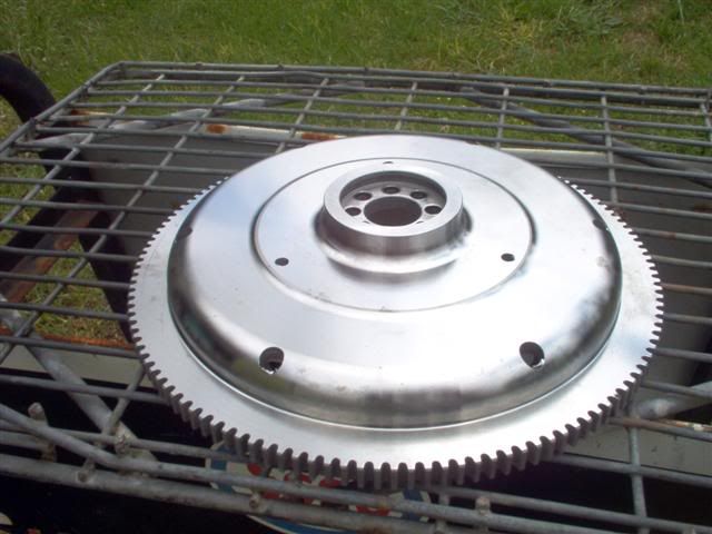
....by taking measurements from the thrust surface of the rear bearing to the crankshafts end, and the depth of the cranks seating depth in the
flywheel we were able to calculate the thickness of the three shims needed to set end play (.004") worked a treat!....did you know one of the 8
dowels is offset so it can only go on the crankshaft one way? (match balanced)....and man, it's a tight fit!!!!!!!
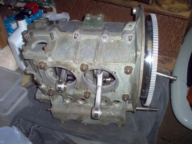
[ Edited on 13-12-06 by dumone ]
|
|
|
 hellbugged hellbugged
A.k.a.: Daimo Pell
23 Windows of Awesome
48's and straight cuts
       
Posts: 5080
Threads: 116
Registered: April 17th, 2003
Member Is Offline
Location: Nambucca Valley NSW
Theme: UltimaBB Psyche Blue
Mood: Couldn't care less
|
| posted on December 13th, 2006 at 09:38 PM |
|
|
deck height????
with the bottom end pre assembled, it's time to look at the deck height and work out how to set a 8.5:1 compression ratio.....
the pistons and cylinders needed washing first.......
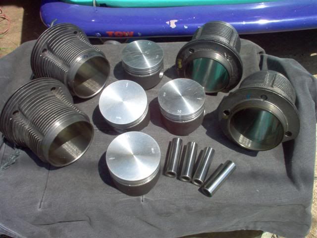
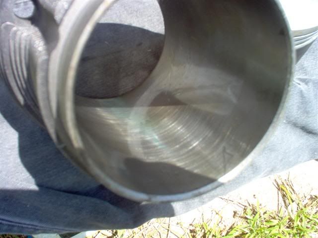
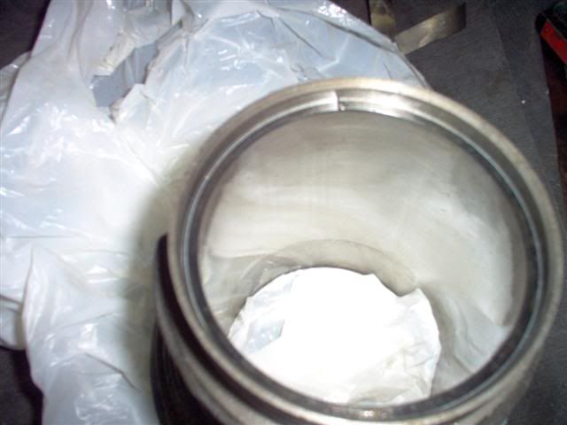
90.5mm pots honed by bergs over 15 years ago! correct storage means the cross hatch pattern left by this honing is still good .....cross hatch pattern
is clear to see...luurvely, one less job!.....
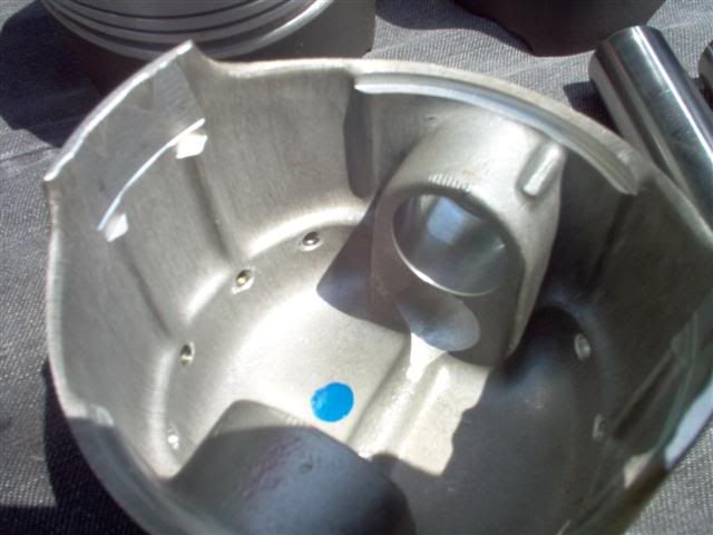
pistons have also been "matched balanced"......you can see were material has been taken out above the gudgen pin seat, to make each pistons weight
equal ...the one which was lightest of the set (benchmark) remains untouched in this area....
ALL rings were individually laid into the ctylinders and their end gaps checked.......all good!....
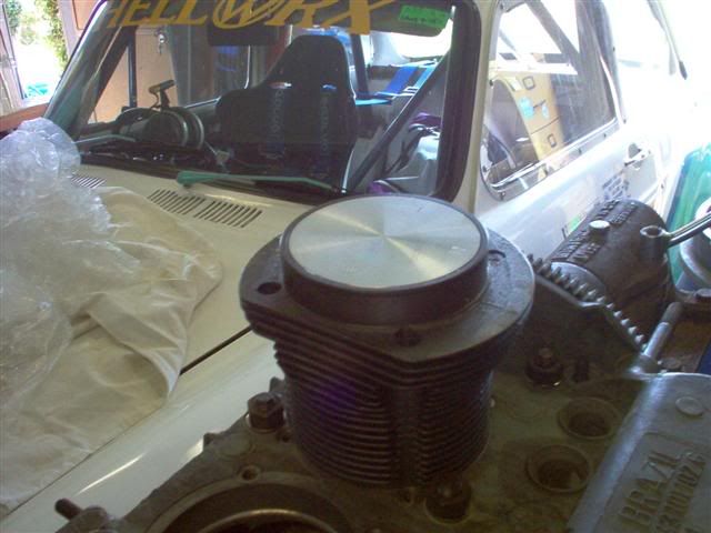
so what about the deck height/compression prospects??
the crankcase had the barrels mounting surface machined at bergs....this re-introduces a proper width seat after the spiggot holes have been machined
to accept the larger O.D barrels......it turned out this area was machined down to provide a zero deck heoght with the supplied P & B set......happy
days- a .040" spacer combined with the CC's of my heads, will provide a minimum tollerence deck height along with the desired 8.5:1 compression
(which was calculated as suitable for 97.5 octane fuel)....
[ Edited on 13-12-06 by dumone ]
|
|
|
 hellbugged hellbugged
A.k.a.: Daimo Pell
23 Windows of Awesome
48's and straight cuts
       
Posts: 5080
Threads: 116
Registered: April 17th, 2003
Member Is Offline
Location: Nambucca Valley NSW
Theme: UltimaBB Psyche Blue
Mood: Couldn't care less
|
| posted on December 13th, 2006 at 10:03 PM |
|
|
all this is aiming towards getting the "bottom end" ready for final assembly...what else needs 'doin?....
deep sump fiddling...
reving the V.W engine well past it's factory design will introduce oil starvation issues......the factory sump will drain itself before the oil can
return to the pick up area via nothing more than gravity (hard cornering dosn't help either and there will be more solutions to this later) BEARINGS
NEED OIL!....solution-an extended sump!...
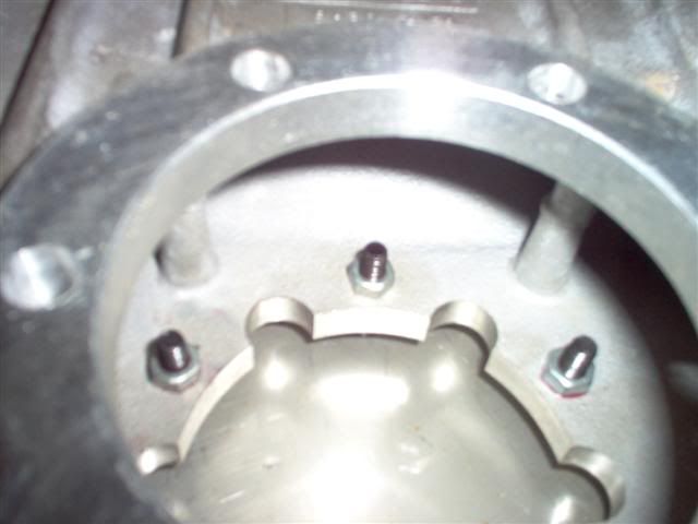
being an older design, mine needed some updating.i want to use the later style "step nuts" so as to utilse a longer holding thread. i need to drill
the mounting holes out....
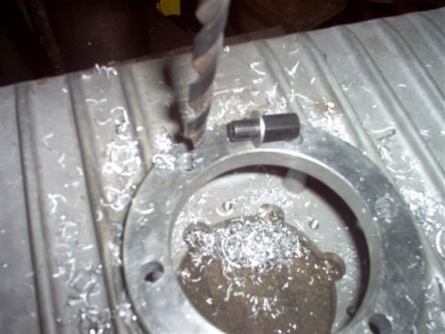
...loctite some longer studs into the engine case....
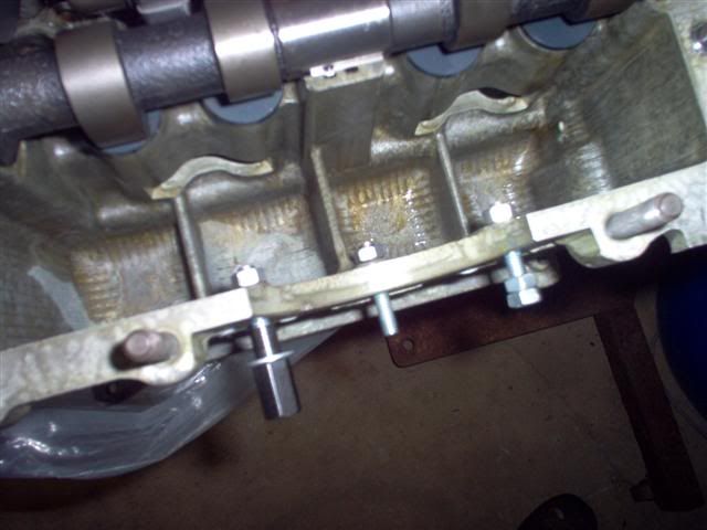
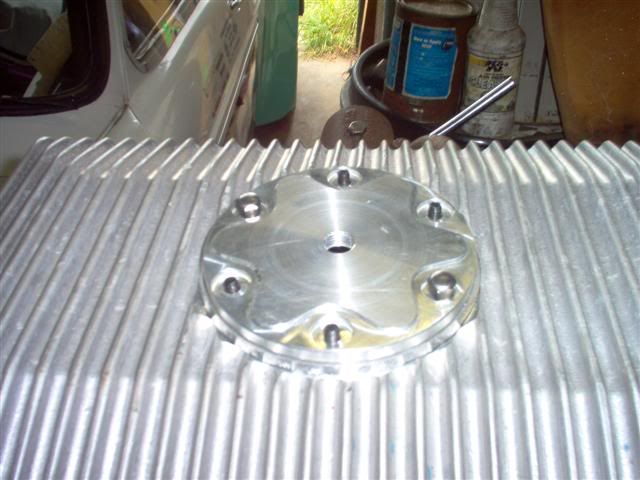
and some into the sump bottom, leaving the correct amount of thread sticking out on the bottom side, so the factory acorn nuts won't bottom out
before sealing the oil in ......
all good....
|
|
|
 hellbugged hellbugged
A.k.a.: Daimo Pell
23 Windows of Awesome
48's and straight cuts
       
Posts: 5080
Threads: 116
Registered: April 17th, 2003
Member Is Offline
Location: Nambucca Valley NSW
Theme: UltimaBB Psyche Blue
Mood: Couldn't care less
|
| posted on December 13th, 2006 at 10:27 PM |
|
|
oil pick up tube needed to be extended to match... it was removed and braised up......
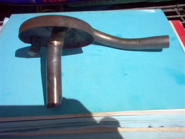
it also needed bending to aim at the center of the sump plate. (factory pick ups often don't and the extension amplifies this). the priciple behind
the "cow magnet" is that it will stop any "hard" metals going thru and damaging the oil pump gears and body. softer materials will be easily
lunched by the pump and strained out by the remote filter, which is the first stop after the pump, before they are able to stuff the rest of the
motor.the extended pick up was "loctited" back into the crankcase and it's holding stud permanantly locked down....
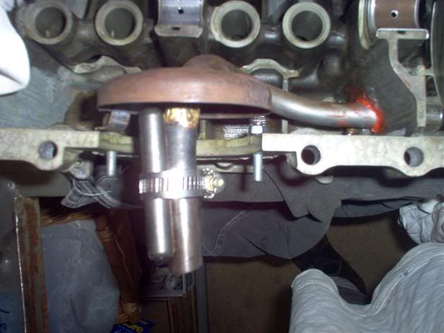
"aim" of pick up checked out good.....step nuts worked well after their washers were ground down on the outside edge (the flange in the older sump
didn't allow for these).....they sure are easier to get started on the thread with fat fingers, are too big to fall into the sump of a sealed bottom
end and provide a lot more peace of mind than tiny M6/10mm spanner nut....win win!....
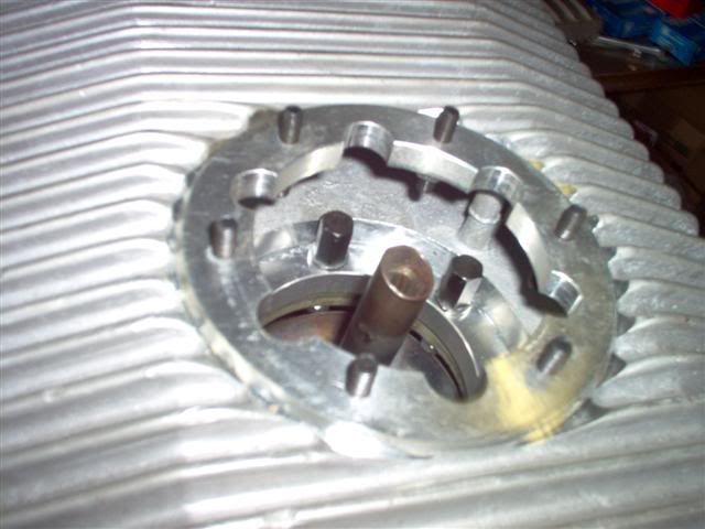
whilst fiddling with threads and loctite, the opportunity was taken to back out the two studs at the case front. this was the only area that couldn't
be machined deep enough for the larger washers and nuts of the modification
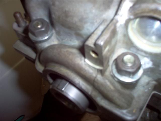
[ Edited on 13-12-06 by dumone ]
|
|
|
 hellbugged hellbugged
A.k.a.: Daimo Pell
23 Windows of Awesome
48's and straight cuts
       
Posts: 5080
Threads: 116
Registered: April 17th, 2003
Member Is Offline
Location: Nambucca Valley NSW
Theme: UltimaBB Psyche Blue
Mood: Couldn't care less
|
| posted on December 14th, 2006 at 05:20 AM |
|
|
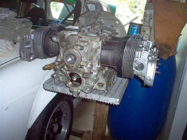
headstuds....
factory 8mm jobbies, black oxidised to protect against corrosion. 4 short, only three medium, 'cause 9 long ones accomidate for the deep seated
outside stud at the number three position.
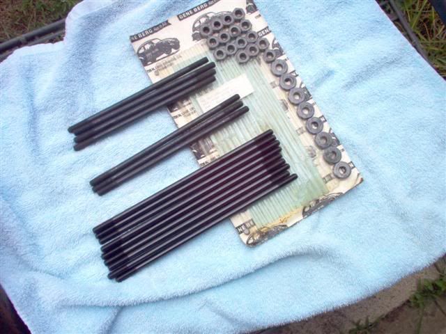
a mock up of the needed length was set up. the studs turn in by hand, and only need to be deep enough for the nut to have a thread full. the studs
don't need to be bottomed out or tourqued into the case inserts, as this could damage them
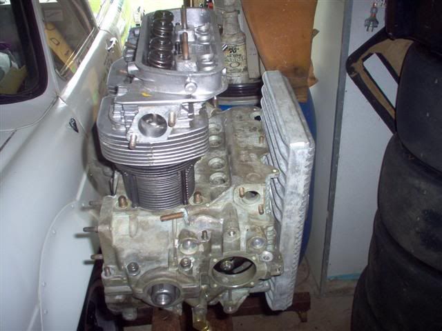
after the height was figured, i took the cylinders out of the way, backed each stud out by a couple of turns, added a couple of drops of "lock
stud", then turned em back in the two turns again.
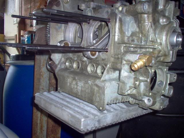
whalaaaa..
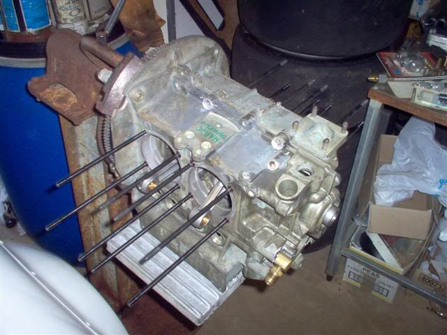
better mock it back up to check before the loctite sets up...exhaust ports are looking rather large too...
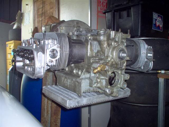
looks good to me. sump looks schweet ...
[ Edited on 14-12-06 by dumone ]
|
|
|
 hellbugged hellbugged
A.k.a.: Daimo Pell
23 Windows of Awesome
48's and straight cuts
       
Posts: 5080
Threads: 116
Registered: April 17th, 2003
Member Is Offline
Location: Nambucca Valley NSW
Theme: UltimaBB Psyche Blue
Mood: Couldn't care less
|
| posted on December 14th, 2006 at 09:31 PM |
|
|
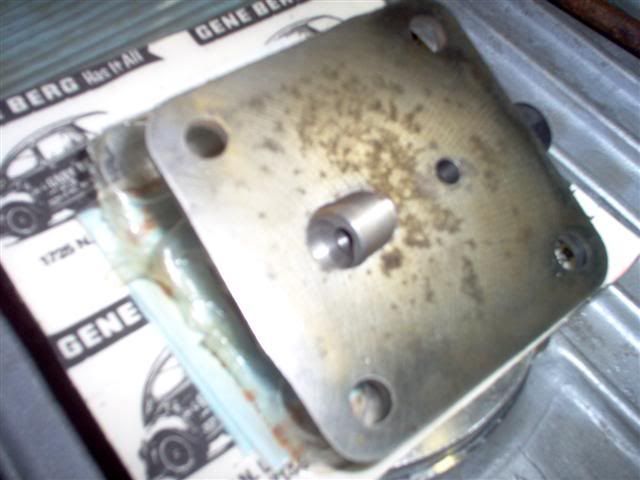
a look inside the pressure relief oil pump cover. cold oil causing excessive pressure in the external lines is relieved back to the suction side of
the oil pump. cool.
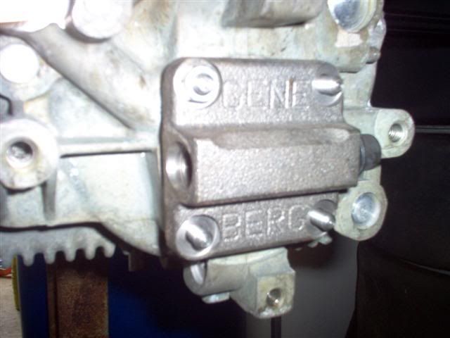
...and the other side...studs were locked in at the necessary length.
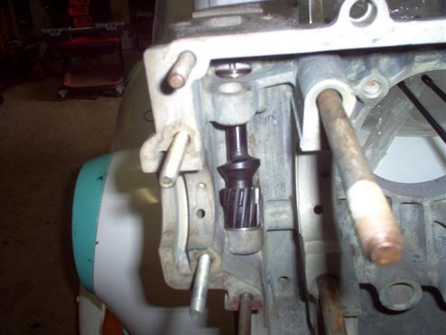
dizzy drive gear has been shimmed, checked for binding issues and timed ready for assembly....you can just pick the oil slot in the bottom of the
distributor is in the correct position
[ Edited on 14-12-06 by dumone ]
|
|
|
 hellbugged hellbugged
A.k.a.: Daimo Pell
23 Windows of Awesome
48's and straight cuts
       
Posts: 5080
Threads: 116
Registered: April 17th, 2003
Member Is Offline
Location: Nambucca Valley NSW
Theme: UltimaBB Psyche Blue
Mood: Couldn't care less
|
| posted on December 19th, 2006 at 05:38 PM |
|
|
a final check on the CAM end play with the dial idicator...... a 'lil over .002"
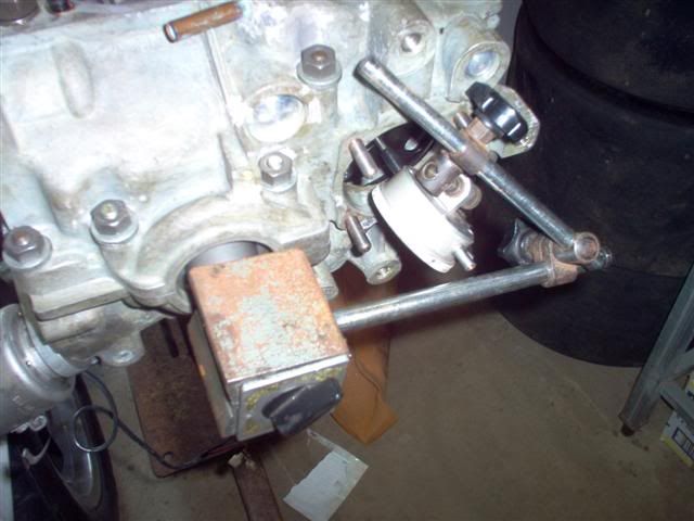
no more excuses, grabbed some of my old mates,
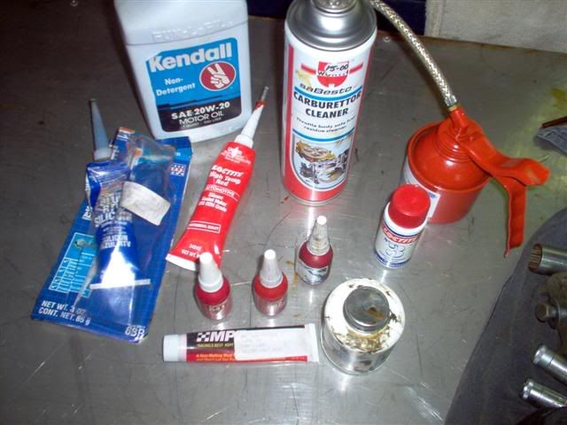
loctited the rod bolts at 24ft/pd, and cam bolts at 24ft/pd......pulled it all down and cleaned it again.
then!!!!!!!!
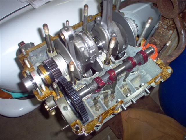
i like that piccie ....i can see i remebered the 6 orings, cam plug,
break in lube and even telll the bearings are sitting home!......better get the top on before it sets.... ....i can see i remebered the 6 orings, cam plug,
break in lube and even telll the bearings are sitting home!......better get the top on before it sets....
six center main (19mmm nuts w/ washers) were tourqued, in a criss cross pattern, to 32 ft/pd!!!.. the outer (15mm headstud size nuts and washers) were
set at 20ft/pd!!!!!!!!.. lifter clips held the cam followers in place
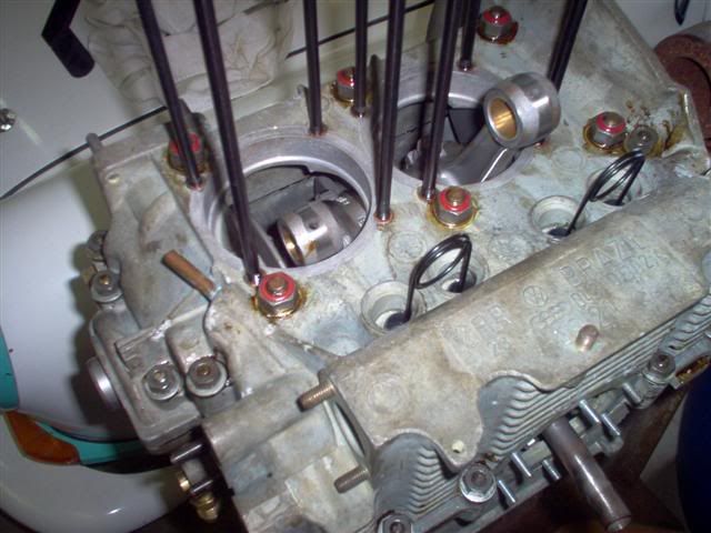
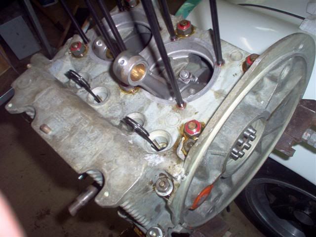
[ Edited on 5-2-07 by dumone ]
|
|
|
 hellbugged hellbugged
A.k.a.: Daimo Pell
23 Windows of Awesome
48's and straight cuts
       
Posts: 5080
Threads: 116
Registered: April 17th, 2003
Member Is Offline
Location: Nambucca Valley NSW
Theme: UltimaBB Psyche Blue
Mood: Couldn't care less
|
| posted on December 19th, 2006 at 05:54 PM |
|
|
"borrowed" gallery plug was replaced to make the pump full flow again and oring on housing (rear) fitted....
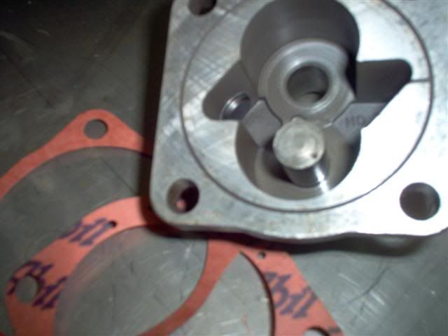
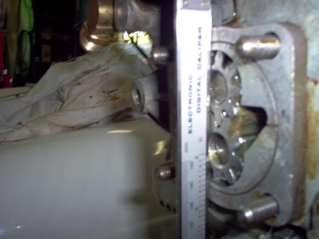
dry build ups make these bits easy....... having previously checked cam/pump clearance and gear depth, all that was needed was a quick check with a
straight edge........all flush. gears were smeared with grease to help prime when first cranking (they weren't designed to pump air)
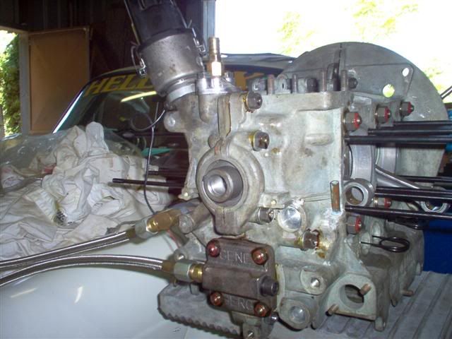
 looks the same as a couple of weeks ago, with the addition of a dizzy,
fuel pump breather and oil lines. at least i can't take any more boring bottom end piccies for the next few years looks the same as a couple of weeks ago, with the addition of a dizzy,
fuel pump breather and oil lines. at least i can't take any more boring bottom end piccies for the next few years
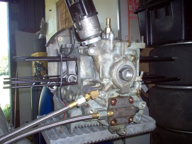
[ Edited on 19-12-06 by dumone ]
|
|
|
 koolkarmakombi koolkarmakombi
Veteran Volks Folk
enkarmarising
    
Posts: 2078
Threads: 158
Registered: June 16th, 2003
Member Is Offline
Location: viva brisvegas
Theme: UltimaBB Pro Blue ( Default )
Mood: do you see the bats?
|
| posted on December 19th, 2006 at 07:32 PM |
|
|
pure dub porn mate!
This disclaimer does not reflect the thoughts or opinions of either myself, my company, my friends, or my dog: don't quote me on that; don't
quote me on anything; this disclaimer is subject to change without notice; text is slightly enlarged to show detail; resemblance to actual persons,
living or dead, is unintentional and coincidental; dry clean only; do not bend, fold, or mutilate; anchovies or jalapenos added to this disclaimer
upon request; your mileage may vary; no substitutions are allowed; for a limited time only while supplies last; offer void where prohibited; this
disclaimer is provided "as is" without any warranties expressed or implied
|
|
|
 hellbugged hellbugged
A.k.a.: Daimo Pell
23 Windows of Awesome
48's and straight cuts
       
Posts: 5080
Threads: 116
Registered: April 17th, 2003
Member Is Offline
Location: Nambucca Valley NSW
Theme: UltimaBB Psyche Blue
Mood: Couldn't care less
|
| posted on February 5th, 2007 at 07:23 PM |
|
|
back again.....
flywheel seal was pushed in with this handy "little" tool,
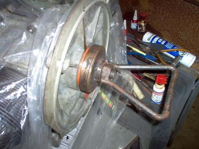
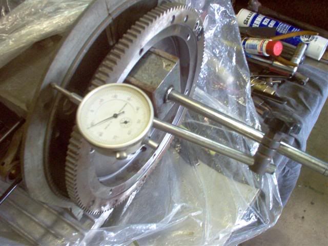
after graphite coated oring was installed, then oiled in the flywheel it was tightened up and endplay checked out at .004"
6 1/4 pound "equalizer"pulley , super pulley bolt & dual bevillie spring washers ....why?, these washers wont bend or crush when torqued to even
100ft/pd (be sure of your cranks quality first tho ) )
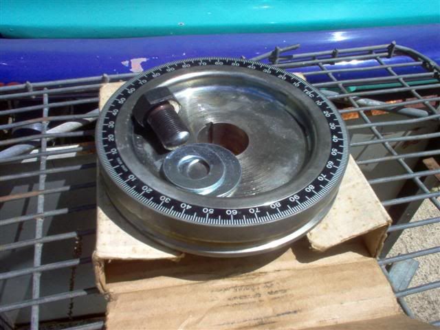
tourqued up to 75ftpd to check for TDC...
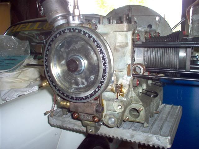
turning the crank clockwise and stopping 5degrees from the marked TDC, then i wound in the bolt on the deck plate till it just touched the
piston...........then the crank was turned anti-clockwise till the piston again touched the bolt on the other side of TDC........the middle of these
two readings is the "corrected" TDC position on the pulley
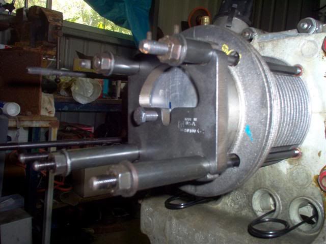
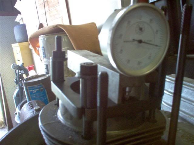
now with the pulley checked, the crank was positioned at true TDC and the deck height measured....1mm or 0.040" all good!
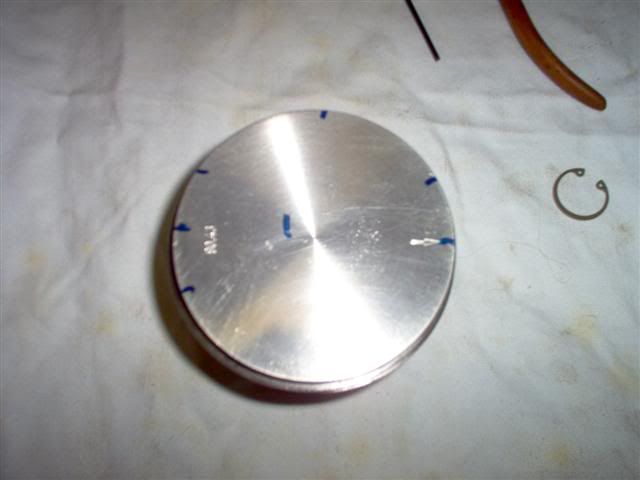
pistons were marked to set the placement of the ring gaps......the small arrow on the right must point to the flywheel, this is how i staggered the
gaps
oil ring (groove closest to engine case)
bottom scraper at 2 o'clock
expander at 12o'clock (these are painted red and green on each end so when installed you must see both colours otherwise it is overlapped)
top scraper at the 10 o'clock position
second ring, total seal(two parts)
primary ring gap at 2 o'clock (top part)
second seal ring was peeled in underneath with it's gap at 8 o'clock, or 180deg. away from the primary gap
top compression ring
the gap here was again positioned at 10 o'clock
:blah:blah:blah really......
[ Edited on 5-2-07 by dumone ]
|
|
|
 Dasdubber Dasdubber
A.k.a.: Alan Agyik
23 Windows of Awesome
DAS Resto Haus
       
Posts: 5746
Threads: 289
Registered: August 26th, 2002
Member Is Offline
Location: Gold Coast
Theme: UltimaBB Pro Blue
Mood: feeling fine...
|
| posted on February 5th, 2007 at 07:33 PM |
|
|
Not blah blah blah at all mate - I'm enjoying seeing it all come together! Slow and steady wins the race 
|
|
|
 hellbugged hellbugged
A.k.a.: Daimo Pell
23 Windows of Awesome
48's and straight cuts
       
Posts: 5080
Threads: 116
Registered: April 17th, 2003
Member Is Offline
Location: Nambucca Valley NSW
Theme: UltimaBB Psyche Blue
Mood: Couldn't care less
|
| posted on February 5th, 2007 at 07:55 PM |
|
|
thanx Alan.........it all got to me for the first time today, wanted the heads on,but alas, maybe tomorrow....then i can flange the exhaust so it can
be coated and plan how the 4 rocker cover oil drains need to be routed back to the sump....
more today, here's the different colours on the oil expander...
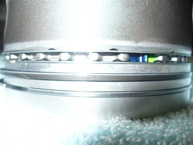
you can see here how the total seal works....this ring was one of the originals with the P & B set and has been converted to total seal....the bottom
of the ring is precision "ground" about 2/3 of its depth, leaving a step on its inside diameter (not visible here), then another ring sits on this
created seat to provide the "gapless" effect:thumb
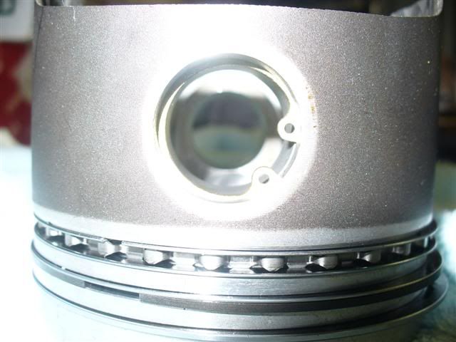
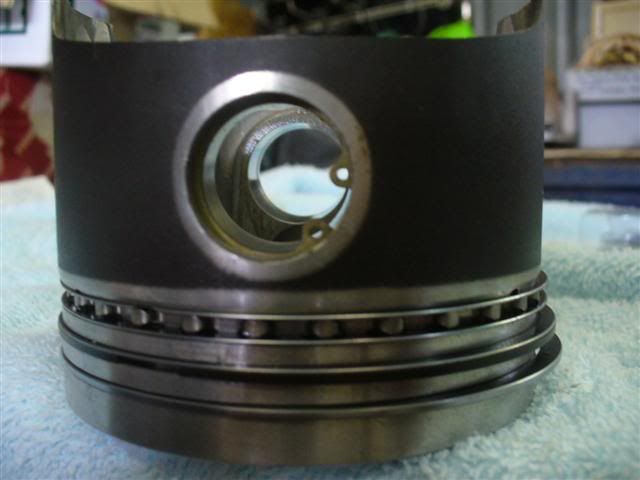
internal circlips are my preference over the original "wire" pin keepers....being a "stamped" item, they must be installed with sharp side away
from gudgeon pin
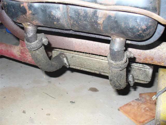
rocker oil drains i speak of will be set up similar to this....returning the oil that gathers in the covers straight back the deep sump to avoid oil
starvation due to high R.P.M and cornering G-forces
[ Edited on 6-2-07 by dumone ]
|
|
|
 hellbugged hellbugged
A.k.a.: Daimo Pell
23 Windows of Awesome
48's and straight cuts
       
Posts: 5080
Threads: 116
Registered: April 17th, 2003
Member Is Offline
Location: Nambucca Valley NSW
Theme: UltimaBB Psyche Blue
Mood: Couldn't care less
|
| posted on February 6th, 2007 at 06:45 PM |
|
|
wanted to check how the "cool tinz" fitted, they had to be clearenced because the main studs interfered with em........
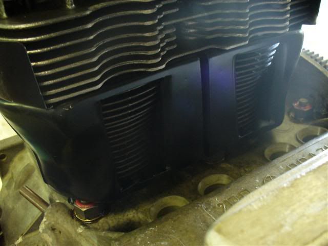
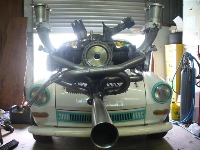
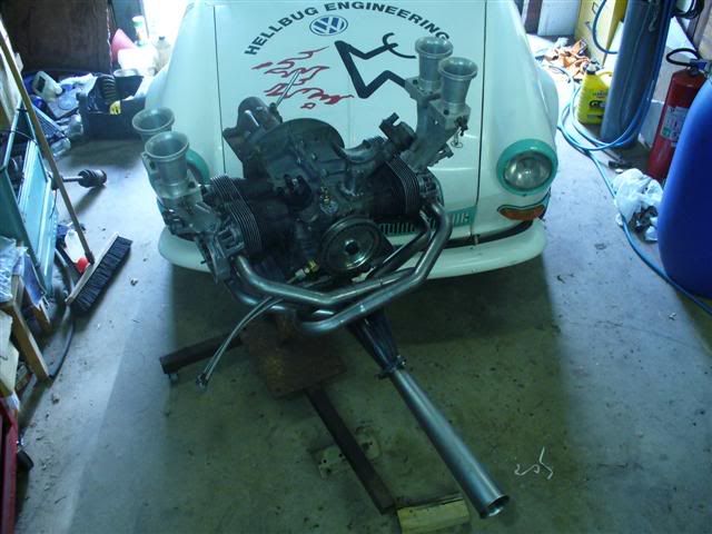
at this point, a self inflicted golf ball lump on my noggin got me thinking my luck was out for the day.......i decided not to install the cylinders,
but continue along with mocking and see how the exhaust checked out.....enjoy, i did!!!
The story by Jeff on these T.B's
All the way along, speedway racers have used mechanically run fuel injection (PI) pumps (the pump was actually belt driven off the front pulley) which
then pressure fed alcohol to the injectors. The mixture settings were a 'black art', changed by the fitting of larger or smaller pills. This system
worked really well compared to carburettors for methanol guzzling flat out racing type applications but was as subtle as a fart in the state library
when it came to daily driver applications.
Volkswagen has used (on some models more successfully than others) varying Bosch fuel injection systems
The early TLE T3 Volkswagens and 76 to 82 two litre air cool’ds ran the Bosch 'D' Jetronic and 'e' Jetronic respectively. The injectors tended
to wear relatively quickly and the system ran lean causing overheating, premature engine wear and burnt valves. More than half of the models fitted
with this model PI would now have been converted to carbies
The 1900 and 2.1 waterboxers ran Digijet and Digifant systems respectively; GTI Golfs—L Jetronic; VR6 Golfs— Motronic; Audis varied from KE
Jetronic to L Jetronic systems.
As can be seen there were many and varied systems manufactured mainly by Bosch. However, they did have mixture trims but could not be drastically
'retuned' to take into account larger capacities, long duration cams etc and that means all the nice hot up work that we VW loonies do to our motors
to get them to perform and goooooo!
The PI system that I am writing about here is the Haltech F3 Programmable Fuel Injection (HPPI). This system uses a very sophisticated programme that
is accessed through any IBM compatible 386 or 486 laptop computer.
Don't think for a moment it is a job that you can do with a few mates on Saturday arvo' with a case of beer and a few tools. It definitely is not,
but by the same token if you take you time, plan it out and get some correct advice from someone who has fitted one, the job is not very daunting.
This is especially so now that PPI has been around for about six or so years and all the ancillary parts are pretty well available off the shelf or
can be sourced second hand from a wrecker of late model cars.
The great advantage of PPI is the varying applications that it can be matched to, such as; Multiple throttle body direct port injection, single
throttle body direct port injection, single throttle body single injector injection, single throttle body direct port turbo intercooled, multiple
throttle body direct port supercharged, single throttle body direct port staged (second set of injectors phased in at say 1.0. bar boost ), turbo
intercooled, single or multiple throttle body direct port, staged injector supercharged. The last two can be set up so that the second set of
injectors can be programmed to come on at any rev point or pre-determined boost pressure.
Add to this the newer systems which allow for total engine management i.e.; timing function as well, you could very easily get that retard on your
dizzy when the boost comes in, to stop all that pinging and detonation on a boosted engine system. Basically they can do any configuration engine!
Full stop!
Once upon a time there were two VW psychopaths... In 1988 Joe Smith and myself were racing the 'Bug out off Hell" race car under the Rogwin
Motorsport banner in the NSW Hill Climb Championship. As the racing fever got hotter and hotter we kept upping the ante to try and catch the three
litre Porsche of David Withers (eternal optimism had us entered in the 2-3 litre Road Registered Class in a 1904 cc 'dub (74 x 90.5). ( Funny, the
2161 cc (84 x 90.5) motor never did eventuate that year). We had started off with 45 Dell's and standard valve ported Berg heads and ended up with a
set of 48 IDA's (a friend had bought them back from the States and Henry Spicak had set them up for us) and a set of Mark Walker 40 x 37.5 ported
heads. The passion for speed was still there as David ended up taking out the championship by seven points; Joe and myself finishing third and second
respectively. We must have made an impact coz' Porsches were no longer allowed to run the Road Registered class only as Marque Sports Cars for
1989.
It was during the later half of'88 that a friend of a friend (Wayne Glasser) had started taking a fair bit of interest in our racing activities and
was calling around a couple of days a week hassling us to try one of the new Haltech systems. I cannot remember what I had sold but the money from its
sale went into the purchase of Haltech F3 unit number 25.This was early days for PPI and I hadn't yet come to grips with computers so the unit just
sat there for a couple of months.
Besides 1988 being our Bicentenary Year it was also a pretty big year for us with all the racing and the prospect of strutting our stuff in the
hot-mix lap dash battle at Valla Park in August. As it turned out, Jeff and Joe always headed up to Valla early so we could have a bit of a rest
before the VW invasion took place.
Donna Pell had told us that we would have to meet Gene and Dee Berg at Nambucca Railway Station. We were the two free souls up here who had nothing
else better to do. For the previous years all we had heard was "Berg this, Berg that" from Richard so we joked about being like Moses and having to
go to the station and receive the Ten VW Commandments (For those of you who don't know Richard, he has the ability to talk a Tom Thumb bunger up to a
Hiroshima H bomb blast. There's no disrespect there Richard but you had us feeling pretty awed out.)
We picked up Gene and Dee and had a great night playing carpet bowls in at the Valla Resort and talking big motors. We talked more after the practice
session on the Friday and had soon ordered a set of 44 x 37.5 heads, 84 wedgemated crank and flywheel, Carrillos etc. Over the weekend I had told Gene
about this new high tech HPPI system that we had bought. He was excited about the concept and agreed that if it did do what was claimed it would be a
world first—he couldn't come to grips with the programme that would be needed to analyse all the different inputs from the sensors and then trigger
the injectors.
As it turned out Gene had been playing around with both turbos and supercharging and mechanical fuel injection—the same old problem—lean out at
elevated boost pressures. And, yes he did have a couple of what he termed 'crude throttle bodies' that would fit onto a 48 IDA manifold. Gene had
always talked about his pile of discarded VW parts that hadn't come up to required standard—well it wasn't until I was over there two years later
that I got to look at the pile—he must have just about tested every VW hot up part that was ever made, as well as the prototypes of his own that
were never made! " Yeah, Sure ' Gene said," you can have them." The first parts on the shopping list found. You bloody beauty! Our friend Wayne
Glasser took the Scat track inlet manifolds and managed to graft on a patch of alloy with his TIC, so we had a platform on which to mount a set of
Camira fuel injector holders. We put the whole set up in the mill, bored a hole and there was our first set of direct port injection manifolds. Now it
was time to fit up the injectors. "Well what size are you going to use"? He asked.
"How much horsepower are you going to make?" asked Wayne. " The old 1904 with 40/37.5 heads, K8 cam, 45 dual Dell's and 1-5/8 merged exhaust put
out 132 HP on the Maztech dyno ' I replied. So this 2161 with 50mm throttle bodies, FK87 cam,1-3/4" race merged exhaust and so on would have to run
at least 200hp." The calculations were done and a set of Bosch 0280 1500 34-060 injectors were fitted up to the now modified manifolds.
Due to the non-availability of such simple parts as fuel injector rails we had to put on the thinking caps to come up with simple solutions. The fuel
rails were made using brass 'T' pieces inter connected with small lengths of PI hose from Tooleys. Not the prettiest fuel rail but it sure worked.
The list went on, a real Hitchhikers Guide to the Retrofitting of PPI onto a Bug.
The throttle bodies that Gene had sent were void of any velocity stack or ram tube so they too had to be made.
It was now time to fit the whole lot up on the motor in the car. The fuel rails stuck out as far as a stallion would approaching a mare. So we pulled
everything out after marking out the areas to be cut. A combination of jigsaw and die grinder seemed to work best and after three attempts and three
hours everything seemed to fall into place. The only other problem was that so much dirt and rocks could get into the engine compartment so we had to
devise a seal to go over the rail. Six self tappers and a hunk of inner tube were all that were needed. A phone call to Finer Filters had the air
filter made up and dispatched in two days.
Now that all the engine compartment manifolding and rails were in place it was time to run the tank fuel line from the tank to the pressure regulator
and return line. We opted to run the fuel injection hose tie strapped to the outer pan rails down each side. The fuel pump and filter were mounted on
the front of the pan opposite the master cylinder. A larger fuel tank outlet (7mm) was made from a barbed fitting to match up with the PI hose. The
return line was routed so it dumped into the petrol tank filler neck—only two late nights for this one!
We had been advised by the powers that be (Mark Boxsell from EFI Technologies ) to fit a fuel pressure gauge to help with the initial Haltech set up,
so a 0-500 kpa VDO gauge was purchased and fitted on the interior of the rear firewall.
Next was the CPU (Central Processing Unit) which was mounted on a one millimetre thick aluminium sheet, acting as the drivers side rear trim. Rubber
mountings were used to isolate the CPU from our race suspension. A mini electrical board was also fitted with fuses and push on terminals to
facilitate the set up.
The fuel pump relays and associated wiring were run and hey presto! The only thing remaining was to run the loom through the firewall into the engine
bay and connect the various sensors. |
Who were we trying to kid? Still more to do.
As the Haltech CPU was set up for MAP (manifold absolute pressure) as opposed to throttle position we drilled and tapped each inlet manifold runner
about two inches under the butterfly shaft and fitted up four brass fittings that would take ordinary braided vacuum line. These hoses were then
connected up to a fabricated metal vacuum box that would average out the vacuum pulses so a static single vac' signal could be fed into the MAP input
of the CPU.
The mixture trims wiring was temporarily run from the CPU along the centre main loop of the roll bar using tie straps. This trim would then be used to
do the initial set up of the fuel curves. When I say initial, the big plan was to fit in a Celica fuel curve, do the start up tuning by ear running
through the rev ranges in neutral, 'til we had a clean running engine that was at least able to drive out of the workshop and onto the road. Once on
the road with an oxygen sensor enema we could then actually get the motor tuned using the mobile exhaust gas analyser (EGA) in conjunction with the +
or—10% mixture trim and laptop computer. At a later date a dyno-session was to be organised to maximise the fuel curves for performance and
power.
Even though we were totally and utterly stuffed by this time adrenaline soon overtook tiredness as the motor fired up first go (after getting the
initial fuel pressure by turning the ignition key on and off end listening to the fuel pump purging all the air from the system. To start off with you
couldn't really rev the motor as there were load points at which the mixture was wrong (it may have been correct for the Celica but not this 2161
boxer with balls.) It was crying out for more fuel! With Wayne Glasser and Mark Boxsell hovering over the EGA and laptop it was hard for us two
mortals to get even a look in as to what was being fiddled with.
Time out for the two Js while the two EFI crazies waved their magic mixture trim over the CPU. Sitting outside the workshop we were numbed by the
feeling of accomplishment, that yes this had been the first HPPI fitted to a VW, our ears were ringing to the sound of the 1-7/8" merged with a
Supertrapp, the whine of the straight gears and our noses were blessed with the aroma of BP100 wafting out from within the bowels of Rogwin.
Before we actually had time to get the caffeine buzz Wayne and Mark had gone through the revs up to 6000 so there were no apparent "no load" dead
spots only the raw bark of a boxer on heat! It had only taken 15 minutes. It was now time for the first test flight.
The oxygen sensor wiring was taped to the bumper, whale tail, roof gutter and then into the cabin. Mark adjusted the seat belt tightly (perhaps he
knew how fast we were actually going to be going or maybe had seen through my hell-bent eyes).
The same process as before was going to be used go though the various rev ranges in 1000 rpm intervals, get all the load points correct using the
mixture trim to change the mixture which was monitored on the EGA. Piece of Piss.
The only major problem encountered was that it was completely useless using the first two gears as they disappeared into the next before you had time
to make any adjustments! Third was chosen as it gave us a little more time. As the load points were tuned the mixture trim came into its own—the
motor would be lead at say 4000 revs—mixture trim 10% richer—wambo—the car took off like I just hit a nitrous button!
Half an hour later the really fine tuning was in progress, third gear disappearing as quick as the full feeling after a Chinese meal. Top gear! More
hassles here, we were starting to go too bloody fast. Poor Mark was stuffed into a standard 1500 low-back seat, had to juggle the EGA on his left
knee, the laptop on the other to adjust the mixture trim and hit the update button on the laptop with Jeff "Rocketman Onion" Unwin driving from 2000
to 7500 rpm in top gear around the back streets of Taren Point. I think Mark must have had a set of "tear off" undies that night, coz the stress was
starting to show!
In between all this trauma we did have some success which the history books proudly show but space limitations here prevent us from reporting.
Over the preceding pages I have referred to load points, an explanation is needed. If you look at a carby, it has basically three load points i.e.;
idle speed and mixture, progression circuitry for transition from pilot to main circuit and the main circuit itself. The 48-IDA is a very easy carte
to tune but does not exhibit much smoothness as it has no progression; basically it should be used for idling in the pits or flat out racing around;
not for driving on the street for which it was never designed. The greater the number of load points the better or smoother the engine will run. What
we found was that the HPPI filled in the gap under which the cam kicked in, by virtue of its 512 load points. It's like a virtual reality
thing—being sucked into feeling that the motor isn't going that hard whereas it has so much more bottom end that the cam step doesn't appear to be
that big at all.
I'll never forget going out to Kurnell in the wet one night with the Bug Out of Hell having 185/70/14 tyres on and being able to squeeze the throttle
at 80kmh in top gear and having both tyres light up and keep spinning through to an indicated 120kays. That’s drivability at a rev range that would
bog down with carbes and a similar camshaft.
In conclusion there is no doubt PPI is here, this is 1994 and we are heading towards 2000 so if you want to upgrade and update your ride so it is as
smooth as all the other 1994 PI cars give PPI a really big sussout before purchasing a bigger set of carbes.By the time 50 minutes had elapsed, we
were adjusting the accelerator pump functions of the Haltech, i.e.: length of time of injection and decay of pump stroke. In five minutes there were
no more flat spots. s it turned out, we never did get to put that motor on the dyno. We ran the 2161 for about four months but had heaps of trouble
with oil surge- the jump from Road Registered Class type tyres to Sports Sedan slicks, stiffer suspension, sway bars and much, much more power soon
turned into a total nightmare. This motor suffered a terminal blow up while representing NSW at the Morwell Interstate Hillclimb Challenge—kicking
two Carrillos out the top of an ARPM case, creating a five piece camshaft, destroying two pistons and liners and digging a three mil' gouge into the
crank!
I can joke now but all was not lost as the pieces ended up becoming the dreaded "Bent Carrillo Trophy" the most feared award at the annual Hillclimb
presentation night. If you "win" this one, you've had the best engine blow, bar none, for the year.
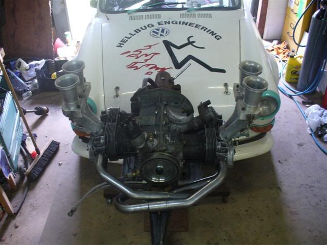
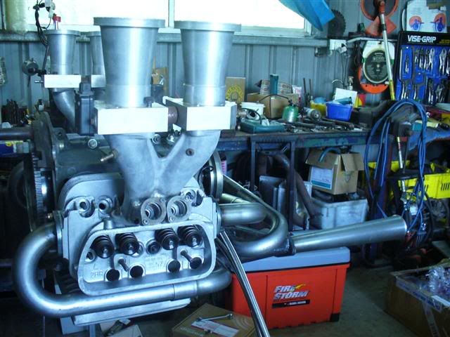
having destroyed a ceramic coated "flimsy brand" set with in months on my current set up, the BERG 1 5/8 set was no comparison, proper 4 into 1,
thick flanges, and tight joins were obviosly a different standard of quality
|
|
|
 pete wood pete wood
A.k.a.: figure itout
23 Windows of Awesome
       
Posts: 6828
Threads: 389
Registered: January 15th, 2004
Member Is Offline
Location: Nth Nth StMarys, Sydney
Theme: UltimaBB Pro White
Mood: upgrades = jackstands
|
| posted on February 7th, 2007 at 06:33 PM |
|
|
that is HORN! 
|
|
|
 VWCOOL VWCOOL
23 Windows of Awesome
       
Posts: 5158
Threads: 235
Registered: June 19th, 2003
Member Is Offline
Location: In the shed... Lake Macquarie NSW
Theme: UltimaBB Pro Blue ( Default )
Mood: happy to help
|
| posted on February 7th, 2007 at 06:54 PM |
|
|
Ooohhh yess... I'm liking those EFI jobbies... :thumb
Pay your debts, CxxT
|
|
|
 koolkarmakombi koolkarmakombi
Veteran Volks Folk
enkarmarising
    
Posts: 2078
Threads: 158
Registered: June 16th, 2003
Member Is Offline
Location: viva brisvegas
Theme: UltimaBB Pro Blue ( Default )
Mood: do you see the bats?
|
| posted on February 7th, 2007 at 06:58 PM |
|
|
beautiful!
love the vise grip wall unit 
do you fit anything above the intakes so it doesnt swallow small children, birds, track marshalls?
This disclaimer does not reflect the thoughts or opinions of either myself, my company, my friends, or my dog: don't quote me on that; don't
quote me on anything; this disclaimer is subject to change without notice; text is slightly enlarged to show detail; resemblance to actual persons,
living or dead, is unintentional and coincidental; dry clean only; do not bend, fold, or mutilate; anchovies or jalapenos added to this disclaimer
upon request; your mileage may vary; no substitutions are allowed; for a limited time only while supplies last; offer void where prohibited; this
disclaimer is provided "as is" without any warranties expressed or implied
|
|
|
 sinecure sinecure
A.k.a.: Sin
Custom Title Time!
Want another... :(
    
Posts: 1031
Threads: 76
Registered: March 30th, 2006
Member Is Offline
Location: Lat 27 S, Long 153 E
Theme: UltimaBB Psyche Blue
Mood: Low, slow and SAD to see it go.
|
| posted on February 7th, 2007 at 08:21 PM |
|
|
Crikey, talk about not doing things by halves. I'll bet there are brain surgeons who are less precise in their work than you. :thumb :thumb :thumb
A POSSE AD ESSE.
I live in my own little world, but it's okay, they know me here.
|
|
|
 hellbugged hellbugged
A.k.a.: Daimo Pell
23 Windows of Awesome
48's and straight cuts
       
Posts: 5080
Threads: 116
Registered: April 17th, 2003
Member Is Offline
Location: Nambucca Valley NSW
Theme: UltimaBB Psyche Blue
Mood: Couldn't care less
|
| posted on February 10th, 2007 at 03:17 PM |
|
|
thanx.
squeezed in an extra couple of hours today. first the cylinders were loaded into the barrels on the bench with one circlip installed and the gudgeon
pin hanging out. sorry no time for a pretty pic .....bead of
prematex blue was run under and on top off the 0.040" spacer.....with all the push rod tubes stretched and seals on, off we went.... .....bead of
prematex blue was run under and on top off the 0.040" spacer.....with all the push rod tubes stretched and seals on, off we went....
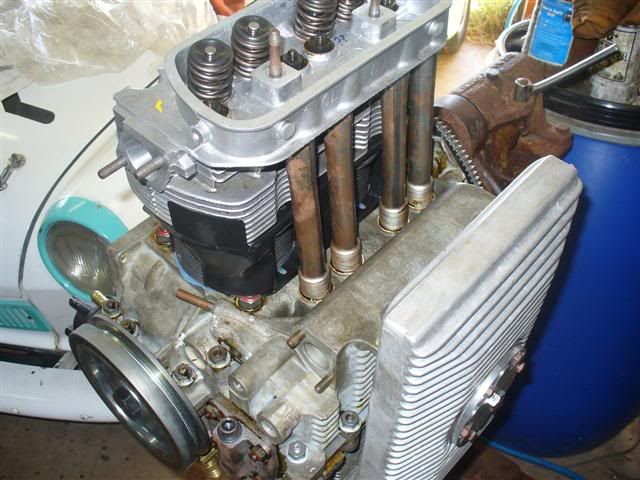
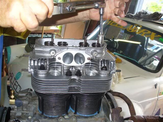
a little trick learnt was to sit the cool tinz on top of the readied pushrod tubes , so they are not forgotten...doh!...wasn't too late.......perhaps a lot more concentration was going
into making sure the arrows on the pistons were pointed to the flywheel, the ring gaps and circlips were positioned correctly.........torqued down 22
pds.... 'lil big ports , so they are not forgotten...doh!...wasn't too late.......perhaps a lot more concentration was going
into making sure the arrows on the pistons were pointed to the flywheel, the ring gaps and circlips were positioned correctly.........torqued down 22
pds.... 'lil big ports
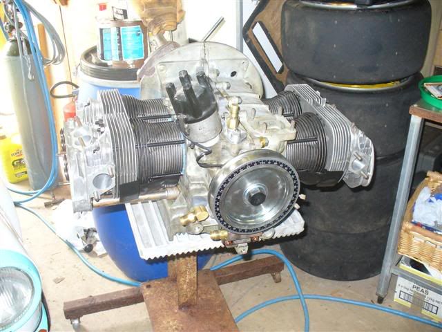
long block is coming along ......thats all torqued and permanent now........stoked
[ Edited on 10-2-07 by dumone ]
|
|
|
 hellbugged hellbugged
A.k.a.: Daimo Pell
23 Windows of Awesome
48's and straight cuts
       
Posts: 5080
Threads: 116
Registered: April 17th, 2003
Member Is Offline
Location: Nambucca Valley NSW
Theme: UltimaBB Psyche Blue
Mood: Couldn't care less
|
| posted on February 12th, 2007 at 05:35 PM |
|
|
pushrods and rocker geometry.....
ooorkay, moving right along, time to work out the pushrod length
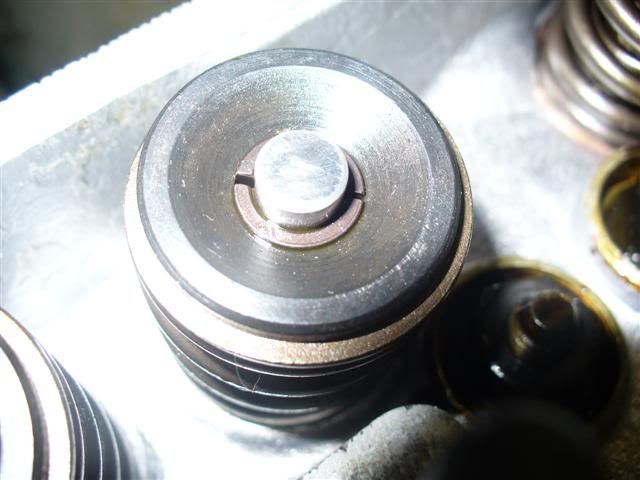
a quicky of the keepers mentioned before, here you can see the gap so the two halves won't rub together and loose grip on the valve
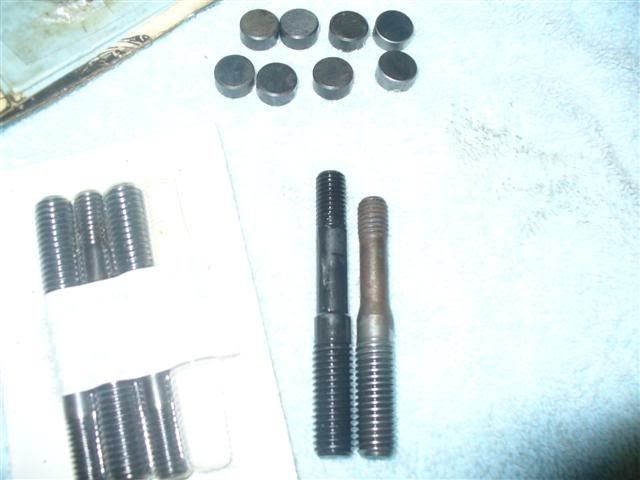
before setting up the rockers the studs were swapped out for these longer heat treated puppies, and lash caps need to be installed too.......
looks the goods there.....
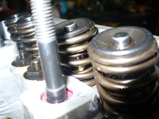
lash caps not only protect the valve stem, but also provide a larger area for the rocker "foot" to work on.
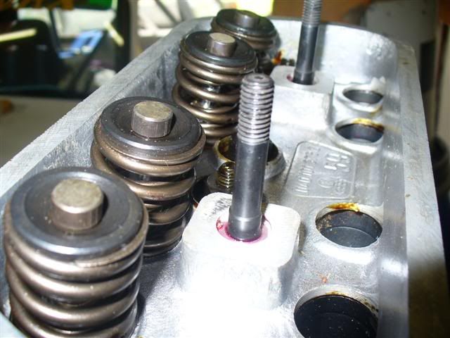
alignment to each valve looks spot on........
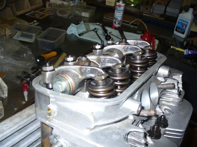
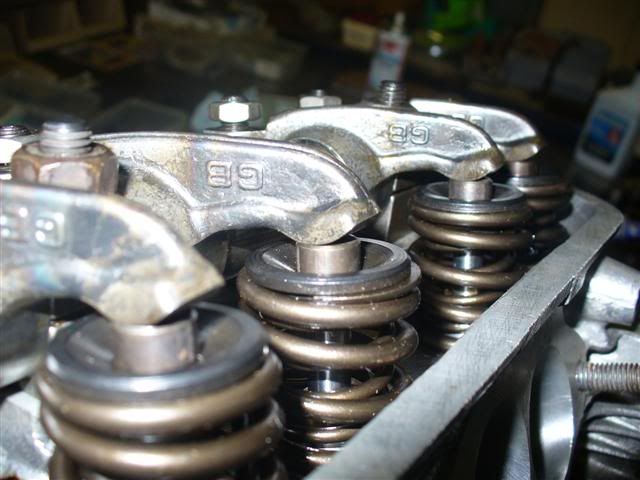
[ Edited on 12-2-07 by dumone ]
|
|
|
 hellbugged hellbugged
A.k.a.: Daimo Pell
23 Windows of Awesome
48's and straight cuts
       
Posts: 5080
Threads: 116
Registered: April 17th, 2003
Member Is Offline
Location: Nambucca Valley NSW
Theme: UltimaBB Psyche Blue
Mood: Couldn't care less
|
| posted on February 13th, 2007 at 06:58 PM |
|
|
hhhmmmmmmmmmm..........
where to start???
what are we trying to achieve?
well we want the rocker foot to use, as close as possible, the center area of the lash cap, by doing so, the valves will not suffer
undue side loads in the valve guides .....consequently wearing them, also wrecking seat sealing...... side play shimms of the rocker assembly will set
the horizontal alignment here....
shimms under the rocker stands (or machining the rocker assembly stands lower).... will change where the "foot" rides on the valve
lash cap in the vertical sense
(things like how deep the valve seats are cut, thickness of the lash caps and length of valves will affect the need to shimm.......or not:o)
we want the rocker foot centered on the valve tip!!
adding to this, we ultimately need the adjusting screw/cups to be horizontal with the pushrodsat half
lift.......this will mean the lift forces will be spread accross the entire cup as the push rod moves the rocker arm up AND AWAY on it's designed
arc...........not setting this up means the pushrod will start with it's load to one side of the adjusting screw, and only put more load
into that side as it lifts, bearly using the topside at all........not good..........
so we want the push rod and valve adjusting cup screw square at half lift !!, this means the best compromise has been
achieved...........ultimately this is achieved by having the correct length push rod
^^my previous post pics will help understand this babble^^
how was i going to get all that right??????
bergs instructions were to simply install the rockers with only 1 1/2 threads of the valve adjustment cup screw sticking out from the
jam/locking nut, being aware BERG adjusters have very little adjustment so to keep the geometry and oiling of them within workable tollerances
....an adjustable pushrod at TDC, and open it up till the rocker touched the valve with your engines future valve clearance------ that would be
the needed length of your push rods.......JOB DONE ????????............would this allow good geometry through the entire lift range??
(as described above) ......my cousin who did a stint at bergs says Clyde could never understand the trouble of doing the half lift method....did this
mean their method worked just as well, maybe it was because BERG parts are designed well enough to work "out of the box"!?!?!?.....maybe i should
email them....NAH!.too easy
the half lift method requires measuring the total ACTUAL lift using a dial indicator..........then checking the geometry at half this
amount (half lift) to see if the pushrods are appropriate length BUT you can't turn the motor over with an adjustable push
rod..........
how can i be sure if i can't do this?....cut and assemble to the adjustables length and see after my new push rods are done.......what if they're
too short/long???....game over??
..........maybe a lighter checking spring would be the answer.....nah.......although having the tool to do a swap with the engine assembled, as i have
done, i want to check the actual springs and avoid the hassle:thumb
maybe some pics will help explain..........
how lucky can someone be?.... if i get the needed length, using the adjustable rod, pretty close with the BERG METHOD (doesn't require spring loads
on adjustable push rod).can i find a assembled set a matching length to check using the HALF LIFT METHOD WITH MY ACTUAL SPRINGS????
..................I'M FEELING LUCKY ........... ...........
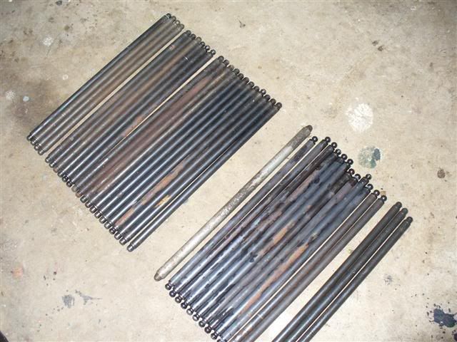
surely, there are soo many to choose from  barely a couple of thou
between some!!.but that will be the difference between a win and loose because of the narrow operating range of the cup adjusters (only 2.5 MAX
threads of adjustment remember) barely a couple of thou
between some!!.but that will be the difference between a win and loose because of the narrow operating range of the cup adjusters (only 2.5 MAX
threads of adjustment remember)
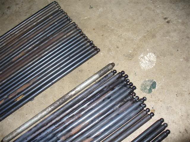
the four together there below are my last chance........earlier i made the decision that time spent removing rockers to gain access to adjust
adjustable pushrod (easier would have been a dry fit of heads without pushrod tubes)......may as well be spent fitting these sets that looked
close......
left of the adjustable are too long, right of the verniers too short.......
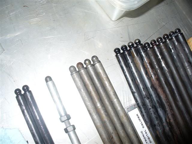
IT'S MY LUCKY DAY!!!!!!!!!!!!!!
they are perfect, with the adjusters threads as bergs describe, i've got .005" valve clearance............now i can look at geometry before i cut
mine to the same length!
a dial indicator needs setting up. using the exhast nuts to mount a bracket, i can read off the side of the spring retainers........
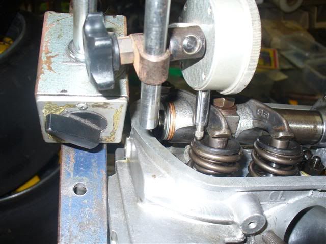
the following shows, that yet again i'm using 15mm head nuts and washers to hold the rockers AND just how' lil thread is above the jam nut, there
ain't much more on the underside of the rocker either.........dial guage is set at zero and crank at TDC so rocker is 0.005" clear of the valve
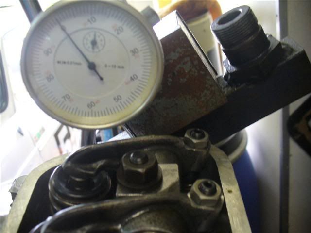
lets see........checking the position of the foot.
AT T.D.C (no lift).......
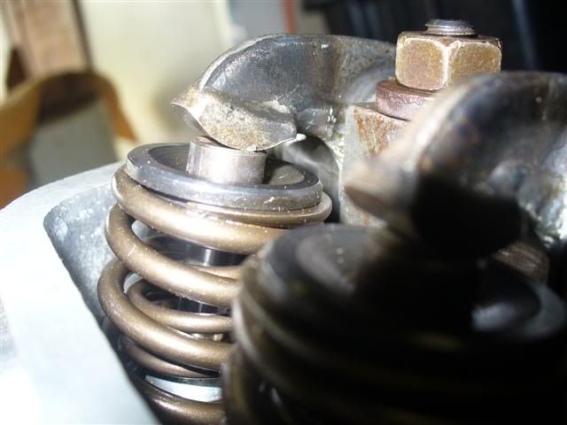
running up to full lift, the measurment was 13.84mm, so at half lift or 6.92mm on the dial, i stopped and took a picture:duh
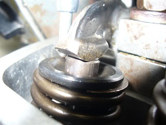
and at the measured full lift now......
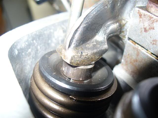
what about on the cup screw end??????
at TDC (no lift).......
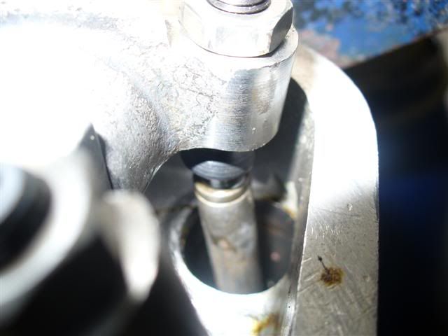
at half lift... that looks square to each other to me
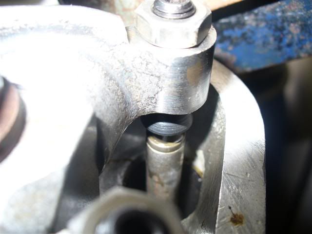
and at full lift....you can see here the relartionship between the cup and push rod has gone either side of square but not too
extreme either way.....
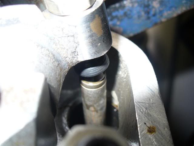
[ Edited on 13-2-07 by dumone ]
[ Edited on 15-2-07 by dumone ]
|
|
|
 hellbugged hellbugged
A.k.a.: Daimo Pell
23 Windows of Awesome
48's and straight cuts
       
Posts: 5080
Threads: 116
Registered: April 17th, 2003
Member Is Offline
Location: Nambucca Valley NSW
Theme: UltimaBB Psyche Blue
Mood: Couldn't care less
|
| posted on February 13th, 2007 at 06:59 PM |
|
|
how does the intake valve look???
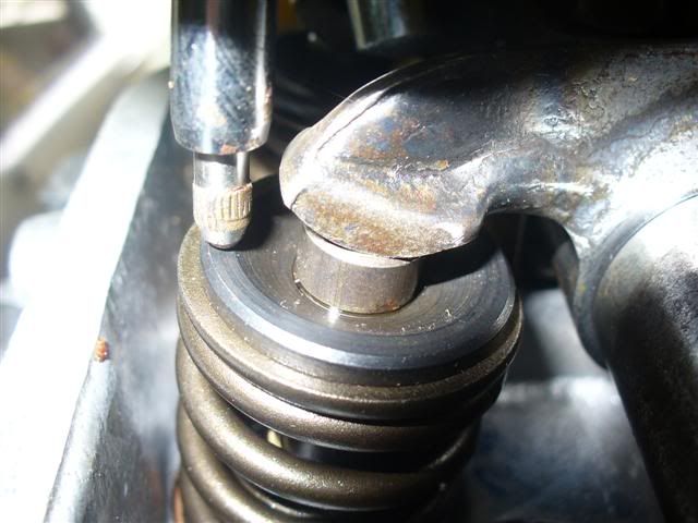
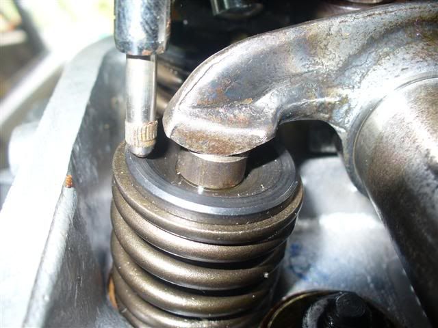
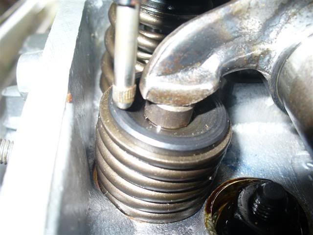
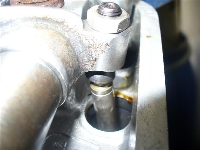
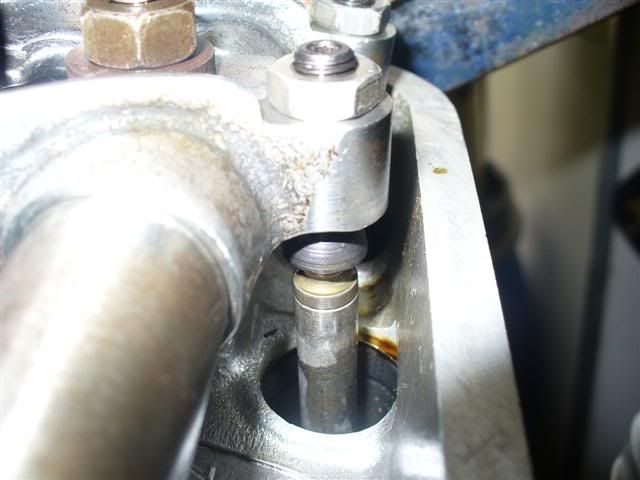
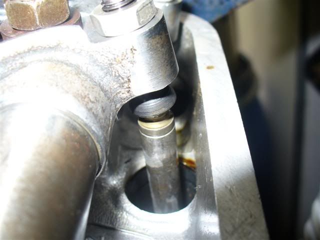
so after all that it looks like the BERG method, although simple, provides the desired reults throughout the lift range...........i wonder if it could
work with other brand components??..........not beig rude, the berg quality is meaning there are few surprises
[ Edited on 13-2-07 by dumone ]
|
|
|
 Craig Torrens Craig Torrens
A.k.a.: Craig Torrens
Scirocco Rare
6 times Australian, 7 times State Hillclimb Class Champion
        
Posts: 8040
Threads: 347
Registered: January 10th, 2003
Member Is Offline
Location: Sydney
Theme: UltimaBB Pro Blue ( Default )
Mood: Time to go Salt lake racing, and actually achieve a result.
|
| posted on February 13th, 2007 at 08:23 PM |
|
|
looking good................love the throttle bodies
|
|
|
 hellbugged hellbugged
A.k.a.: Daimo Pell
23 Windows of Awesome
48's and straight cuts
       
Posts: 5080
Threads: 116
Registered: April 17th, 2003
Member Is Offline
Location: Nambucca Valley NSW
Theme: UltimaBB Psyche Blue
Mood: Couldn't care less
|
| posted on February 13th, 2007 at 10:53 PM |
|
|
thanx Craig, the bodies are from the original flamed hellbug, and were up and running over 20 years ago!!!!!!!...that would be close to the first EFI
bug wouldn't it?........they are billet aluminium made here in Australia (Mark Walker did em ?).......yes they are beautifull big, and classed as
unobtainium.......but i'm working on that part :P...i'm hoping to see some pics of your tricks this year Craig..07 was supposed to a biggy
was it not?........oh and welcome back, i missed ya.well was concerned about your lack of posting anyways
keen observers would have noticed the pushrod tubes only have the one end "crushable. the end at the head is flared to allow room for the pushrods
inside......ratio rockers cause them to move out of center in the tubes....
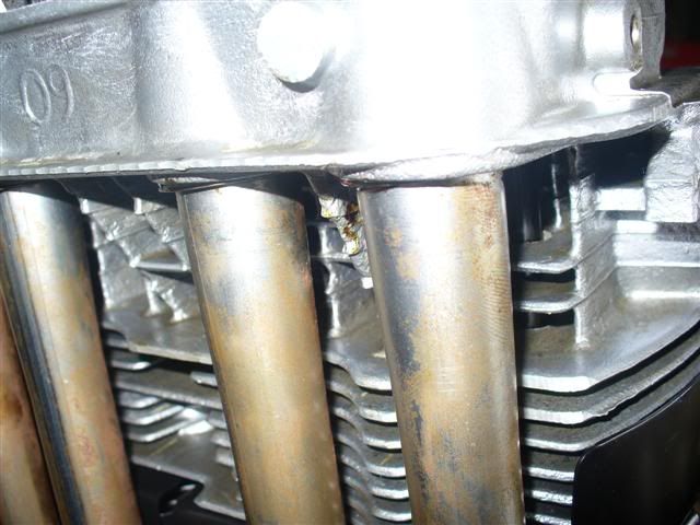
did i need them??????.........
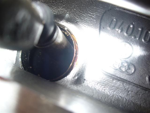
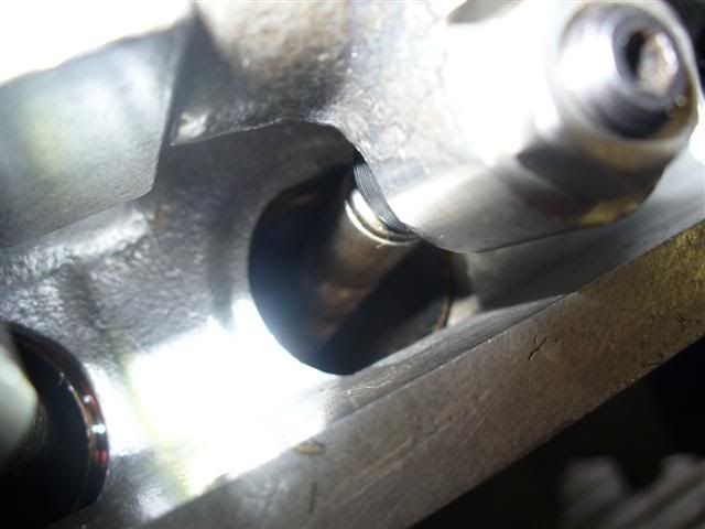
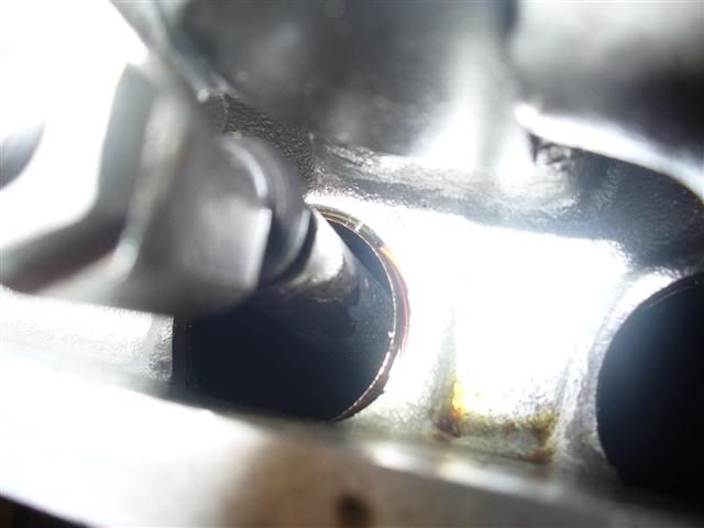
 think so...... think so......
about the lift amount
.343" (8.71mm).....
...at the cam is whats on the tags for the 309 cam....
..with my 1.45 ratio rockers this should then at the valve be....
.497" (12.62mm)
it measured out to be....
.545" (13.84mm) - exhaust valve
&
.548" (13.92mm)- intake valve
why?? well the berg rockers are guaranteed to lift AT LEAST the advertised ratio, and because of the excellent design of the foot area, this ratio
will actually increase towards the tip of this foot......
i'm happy with those numbers,hope they all check out as even, we're looking good here..
next job is to check each valve for measured lift and check the clearance of the valve retainer on the guide top and for the springs coil bind......
|
|
|
 hellbugged hellbugged
A.k.a.: Daimo Pell
23 Windows of Awesome
48's and straight cuts
       
Posts: 5080
Threads: 116
Registered: April 17th, 2003
Member Is Offline
Location: Nambucca Valley NSW
Theme: UltimaBB Psyche Blue
Mood: Couldn't care less
|
| posted on February 19th, 2007 at 06:35 PM |
|
|
so once i found the needed pushrod length, i was able to cut mine to size (3/8"chrome molly/0.035" wall thickness). they needed to be shortened by
.340".......and are only reemed for the heat treated "may west full ball" end enough to be cut .350" from the unassembled end, another stroke of
luck:thumb.
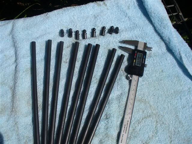
using a dial indicator on the lathe bit, this was done, and the I.D of them de-burred ready for assembly.two lifters are used for installing the
ends.....i took the liberty of using the age old method of fire and ice to make it easier to get them straight at the start........placing the end
balls in the freezer while the rods were left in the sunshine.
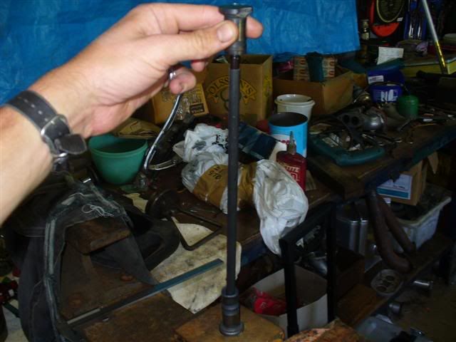
i cut the material beyond the cup in the top lifter to make it easier to watch as the ball was driven home.....
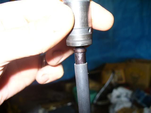
job done...........
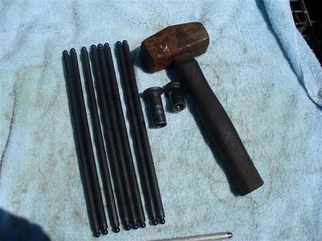
mentioned before, the 1.45 rocker were picked up NOS as a private sale..........the previous owner had a play with the shimm arrangement, leaving too
much side play in the arms for my liking, i wanted it no more than 0.005"........so now it was my turn to play
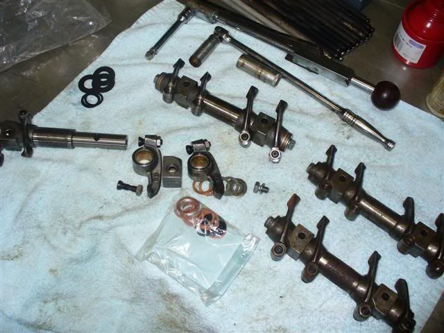
it was a good chance to have a look at how the oiling of the arms is achieved.........you can see just how little adjustment is available of the cup
screw under and above the arm and why this was done so to keep the oliing hole in the screw located correctly..........the jam nuts are tiny so only a
small amount of thread is needed on the outside, that way there will be no tappet cover clearance issues at lift:thumb.........i like the proper
reemed bushings, no rollers there!
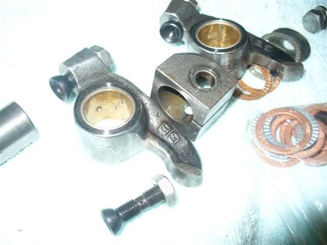
eventually i got the side play i was after, with a maximum of 0.005"..........i had to sand a little on one side of the stand block to get enough
clearence for one of the intake arms........apart from that shimms worked fine.
|
|
|
 pete wood pete wood
A.k.a.: figure itout
23 Windows of Awesome
       
Posts: 6828
Threads: 389
Registered: January 15th, 2004
Member Is Offline
Location: Nth Nth StMarys, Sydney
Theme: UltimaBB Pro White
Mood: upgrades = jackstands
|
| posted on February 20th, 2007 at 12:06 PM |
|
|
very cool. you make it so easy...and cheap. :duh
|
|
|
 hellbugged hellbugged
A.k.a.: Daimo Pell
23 Windows of Awesome
48's and straight cuts
       
Posts: 5080
Threads: 116
Registered: April 17th, 2003
Member Is Offline
Location: Nambucca Valley NSW
Theme: UltimaBB Psyche Blue
Mood: Couldn't care less
|
| posted on February 26th, 2007 at 08:27 PM |
|
|
ummmm, yeah, well Pete................nevermind......
soooooooo, after sitting down and really checking out the intital numbers above, it's looking like those "1.45" rockers are ACTUALLY 1.54's ........that's thrown everything out of whack!! ........that's thrown everything out of whack!!
it's been back to the drawing board/calculator/dial indicators measuring up a new set of lift numbers (now with my assembled pushrods) and binding
issues to see if the springs even have a chance of living with those monster rockers.....................
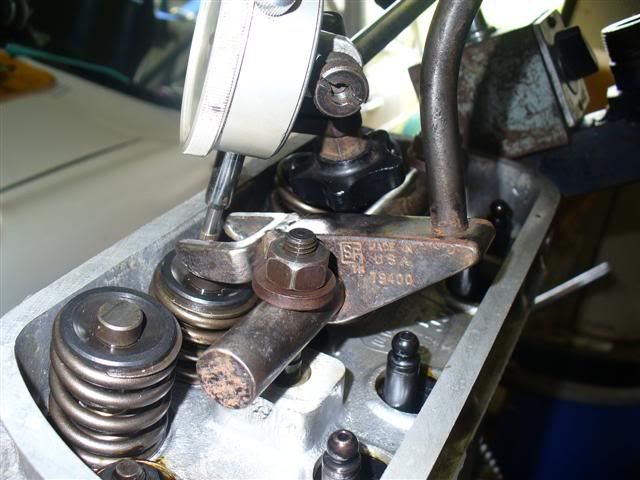
got a new tool working too..........using a spark plug pressurised air bung, this enables spring removal on a fully assembled engine......
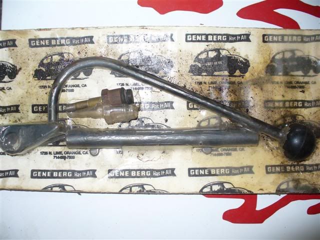
i'll leave that one as NOS for now, because another one floating around has had the tips modified to more of a rockers' shape........ onya
Shimmo:thumb
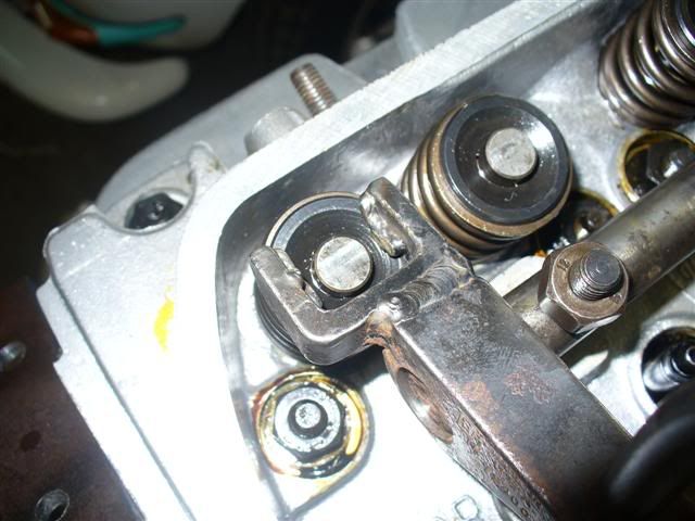
i'm using it to help find "bind" measurements.......
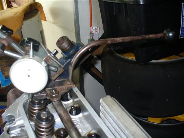
this numbers crunching is doing my head over at the moment..........so is the lack of progress, there are MARS bars riding on a completion date
now:kiss
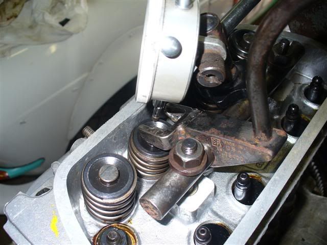
later i will use this to remove the inner spring for "run in" and of course to put them back afterwards
[ Edited on 28-2-07 by dumone ]
|
|
|
 56astro 56astro
Custom Title Time!
    
Posts: 1772
Threads: 74
Registered: August 25th, 2002
Member Is Offline
Location: The Nambucca
Theme: UltimaBB Pro Blue ( Default )
Mood: Pobjoy Powered with twin ignition & soon to be EFI'd
|
| posted on February 26th, 2007 at 08:45 PM |
|
|
Daimo,
Where did ya get the "fuel pump breather" from?

VW car, VW engine ...... keepin it "real"
35MPG on 101.3kPa |
|
|
 hellbugged hellbugged
A.k.a.: Daimo Pell
23 Windows of Awesome
48's and straight cuts
       
Posts: 5080
Threads: 116
Registered: April 17th, 2003
Member Is Offline
Location: Nambucca Valley NSW
Theme: UltimaBB Psyche Blue
Mood: Couldn't care less
|
| posted on February 26th, 2007 at 08:49 PM |
|
|
ohhh come on Astro!....................others do stock em tho, seen em on Georges specials before........
|
|
|
 56astro 56astro
Custom Title Time!
    
Posts: 1772
Threads: 74
Registered: August 25th, 2002
Member Is Offline
Location: The Nambucca
Theme: UltimaBB Pro Blue ( Default )
Mood: Pobjoy Powered with twin ignition & soon to be EFI'd
|
| posted on February 26th, 2007 at 08:55 PM |
|
|
Nuff said.
1 upper-cut to me!


VW car, VW engine ...... keepin it "real"
35MPG on 101.3kPa |
|
|
| Pages: 1 .. 3 4 5 6 7 .. 24 |